8
4. DATA + CS TRAIN
Demo: with:
DOX2025
DOX2040
DOX2100
DOX2xxxB
Test Signal
n°4 : Data + CS train
Nature
2 signals representing a digital frame (data) and a CS (chip select)
Specs
Vpp ≈ 3.4 V - F ≈ 40 kHz (data) - F ≈ 1.5 kHz (CS)
Oscilloscope Settings
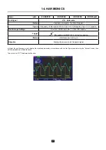
100 µs/div. - MAIN = 1 V/div. - AUX ≈ 1 V/div.
Trigger
on BNC AUX = CH2
Modes
Triggered mode preferable
Objective
Triggering on pulses
a) Adjust the oscilloscope to display simply the 2 signals (time base, sensitivities and triggering source on the BNC AUX = CH2).
Attention, with this type of signal, “Autoset” operation may be aleatory.
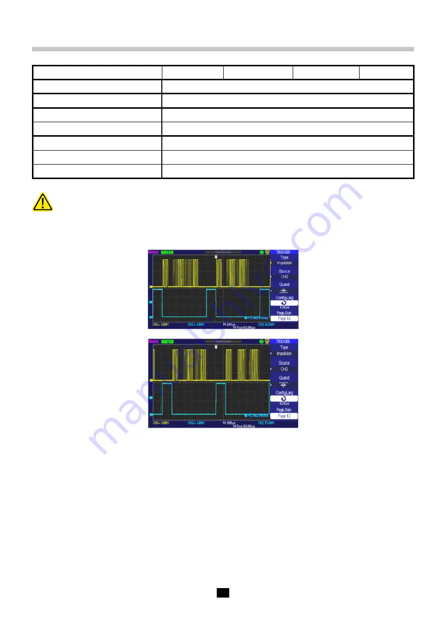
b) We are now going to demonstrate the utility of the pulse width triggers. The example chosen will serve to synchronize to the chip select signal
of the data frame. We are going to trigger by turns on the width of the high level, then of the low level, of the “positive” pulse. In the first case,
triggering will be on the negative-going edge of the chip select and in the second case it will be on the positive-going edge.
c) Observe the first data group after the negative-going edge of the chip select using the
“Delayed”
function.
Example: to display the 2nd group of pulses, we shift the window by acting on the horizontal position.


