13
2.9. MOUNTING
As a logger, the PEL is designed to be installed for an extended period in a utility room.
The PEL should be placed in a well-ventilated room. Temperature should not exceed the values specified in § 6.5.
The PEL can be mounted on a flat ferromagnetic vertical surface using the built-in magnets.
The strong magnetic field can damage your hard drives or medical devices.
2.10. KEY FUNCTIONS
Key
Description
ON/OFF key
Turns the instrument ON or OFF.
Note
: The instrument cannot be turned OFF while connected to an AC outlet or if a recording is in progress.
Control key:
A long press starts or stops recording, enables or disables the Bluetooth link, the Ethernet link, the Wi-Fi (PEL104)
or the 3G-UMTS/GPRS (PEL104).
Enter key (PEL103 and PEL104)
In the configuration mode, serves to select a parameter to be modified.
In the measurement and power display modes, serves to display the phase angles and the partial energies.
Navigation key (PEL103 and PEL104)
These are used to browse the data displayed on the LCD screen.
Table 2
2.11.
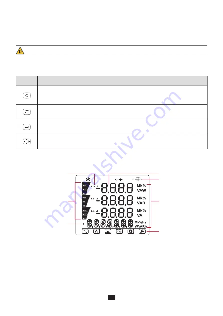
LCD DISPLAY (PEL103 AND PEL104)
Figure 10
Phase
Percentage of the range.
Measurements or display page
titles.
Measured values
Status icons.
Measurement units.
Mode icons.
Summary of Contents for pel 102
Page 1: ...Power energy logger EN User s manual PEL 102 PEL 103 PEL 104 ...
Page 24: ...24 Aggregation period Date and time IP address scrolling Wi Fi address scrolling PEL104 ...
Page 36: ...36 Three phase 3 wire balanced 3P 3W b U12 U23 U31 f P Q S PF P Q S tan ϕ I1 I2 I3 ϕ I1 U12 ...
Page 38: ...38 Three phase 4 wire wye balanced 3P 4WYb I1 I2 I3 V1 V2 V3 VN U12 U23 U31 f P Q S tan ϕ ...
Page 39: ...39 DC 2 wire dC 2W DC 3 wire dC 3W P Q S PF ϕ I1 V1 P Q S tan ϕ P I V VN I1 I2 IN ...
Page 40: ...40 DC 4 wire dC 4W P I1 I2 I3 IN V1 V2 V3 VN V1 V2 VN ...
Page 48: ...48 Two phase 3 wire 1P 3W I1 I2 V1 V2 U12 VN P Q S P Q S ...
Page 51: ...51 P Q S ...
Page 85: ...85 ...


