14
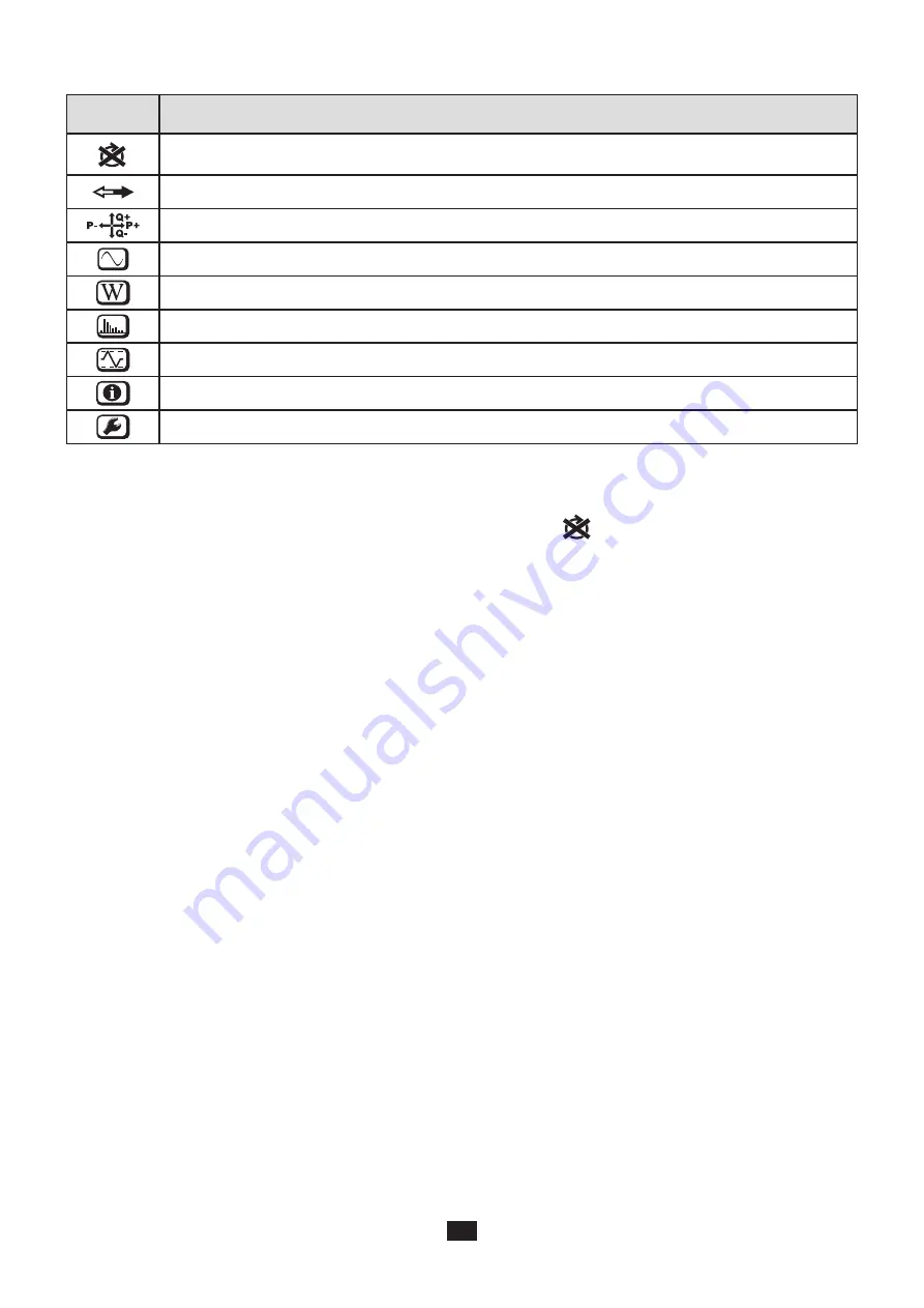
The top and bottom bars indicate the following:
Icon
Description
Phase Sequence reversal or missing phase indicator (displayed only in Measurement Mode, see explanations
below)
Data are available for recording (non-display indicates possible internal problem)
Indication of the power quadrant (see §9.1)
Measurement Mode (Real Time values) (see §4.4.1)
Power and Energy Mode (see §4.4.2)
Table 3
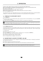
Phase order
The phase order icon is displayed on the LCD only when Measurement Mode is selected.
The phase order is determined every second. If the phase order is incorrect, the
symbol is displayed on the LCD display.
Phase order for voltage channels only is displayed when voltages are displayed on measurement screen.
Phase order for current channels only is displayed when currents are displayed on measurement screen.
Phase order for voltage and current channels is displayed when the other screens are displayed.
The source and load must be parameterized using PEL Transfer to define the direction of the energy (imported or exported).
Summary of Contents for pel 102
Page 1: ...Power energy logger EN User s manual PEL 102 PEL 103 PEL 104 ...
Page 24: ...24 Aggregation period Date and time IP address scrolling Wi Fi address scrolling PEL104 ...
Page 36: ...36 Three phase 3 wire balanced 3P 3W b U12 U23 U31 f P Q S PF P Q S tan ϕ I1 I2 I3 ϕ I1 U12 ...
Page 38: ...38 Three phase 4 wire wye balanced 3P 4WYb I1 I2 I3 V1 V2 V3 VN U12 U23 U31 f P Q S tan ϕ ...
Page 39: ...39 DC 2 wire dC 2W DC 3 wire dC 3W P Q S PF ϕ I1 V1 P Q S tan ϕ P I V VN I1 I2 IN ...
Page 40: ...40 DC 4 wire dC 4W P I1 I2 I3 IN V1 V2 V3 VN V1 V2 VN ...
Page 48: ...48 Two phase 3 wire 1P 3W I1 I2 V1 V2 U12 VN P Q S P Q S ...
Page 51: ...51 P Q S ...
Page 85: ...85 ...


