17
3. OPERATION
The PEL must be configured before any recording. The various steps in this configuration are:
Set up the Bluetooth link, the USB link, the Ethernet link, the Wi-Fi link (PEL104) or 3G-UMTS/GPRS (PEL104).
Choose the connection according to the type of distribution network.
Connect the current sensors.
Define the nominal primary and secondary voltages if necessary.
Define the nominal primary current and the nominal primary current of the neutral if necessary.
Choose the aggregation period.
This configuration is done in the Configuration mode (see § 3.4) or using the PEL Transfer software (see § 5). To forestall accidental
modifications, the PEL cannot be configured while recording or if a recording session has been programmed.
3.1. TURNING THE INSTRUMENT ON/OFF
3.1.1. TURNING ON
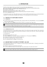
Connect the PEL to a power outlet with the AC power cord and the PEL will turn ON automatically. If not, press the
ON/OFF
key for more than 2 seconds.
The green LED under the
ON/OFF
key turns ON when the PEL is connected to a live supply source.
The battery automatically begins recharging when the PEL is connected to a live power outlet. Battery life is approximately
1/2 hour when the battery is fully charged, enough to cover brief power outages.
3.1.2. TURNING THE PEL OFF
You cannot turn the PEL OFF if it is connected to a power source or if a recording is in progress (or pending). This is a precaution
to ensure that the PEL is not accidently turned OFF when recording and to ensure that the PEL turns on when the power supply
is turned back on after an outage.
To turn the PEL OFF:
Unplug the cord from the power outlet.
Press the
ON/OFF
key for more than 2 seconds, until all LEDs turn on. Then release the
ON/OFF
key.
All LEDs and the display will turn off as the PEL powers down.
If the PEL has supply power present, it will not turn OFF.
If a recording is pending or in progress, it will not turn OFF.
3.2. CONNECTION BY USB OR BY ETHERNET LAN LINK
The USB and Ethernet links can be used to configure the instrument using PEL Transfer software, to display the measurements,
and to upload records to the PC.
Withdraw the elastomer cap that protects the connector.
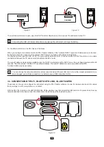
Connect the USB cable provided or an Ethernet cable (not provided) between the instrument and the PC.
Before connecting the USB cable, install the drivers supplied with the PEL Transfer software (see §
5).
Summary of Contents for pel 102
Page 1: ...Power energy logger EN User s manual PEL 102 PEL 103 PEL 104 ...
Page 24: ...24 Aggregation period Date and time IP address scrolling Wi Fi address scrolling PEL104 ...
Page 36: ...36 Three phase 3 wire balanced 3P 3W b U12 U23 U31 f P Q S PF P Q S tan ϕ I1 I2 I3 ϕ I1 U12 ...
Page 38: ...38 Three phase 4 wire wye balanced 3P 4WYb I1 I2 I3 V1 V2 V3 VN U12 U23 U31 f P Q S tan ϕ ...
Page 39: ...39 DC 2 wire dC 2W DC 3 wire dC 3W P Q S PF ϕ I1 V1 P Q S tan ϕ P I V VN I1 I2 IN ...
Page 40: ...40 DC 4 wire dC 4W P I1 I2 I3 IN V1 V2 V3 VN V1 V2 VN ...
Page 48: ...48 Two phase 3 wire 1P 3W I1 I2 V1 V2 U12 VN P Q S P Q S ...
Page 51: ...51 P Q S ...
Page 85: ...85 ...


