21
3.4.2. CURRENT SENSORS
Connect the current sensors to the instrument.
The current sensors are automatically detected by the instrument. It looks at the I1 terminal. If there is nothing, it looks at the I2
terminal, or the I3 terminal.
Once the sensors have been recognized, the instrument displays their ratio.
The current sensors must all be the same, except for the neutral current sensor, which may be different. Otherwise, only
the type of sensor connected to I1 will be used on the instrument.
3.4.3. NOMINAL PRIMARY VOLTAGE
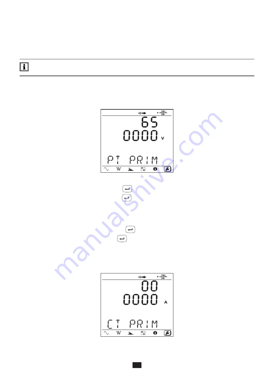
Press the ▼ key to go to the next screen.
Figure 16
To change the nominal primary voltage, press the
Enter
key. Use the ▲, ▼, ◄ and ► keys to choose the voltage, between
50 and 650,000 V. Then validate by pressing the
Enter
key.
3.4.4. NOMINAL SECONDARY VOLTAGE
Press the ▼ key to go to the next screen.
To change the nominal secondary voltage, press the
Enter
key. Use the ▲, ▼, ◄ and ► keys to choose the voltage, between
50 and 1,000 V. Then validate by pressing the
Enter
key.
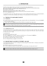
3.4.5. NOMINAL PRIMARY CURRENT
Press the ▼ key to go to the next screen.
Figure 17
Summary of Contents for pel 102
Page 1: ...Power energy logger EN User s manual PEL 102 PEL 103 PEL 104 ...
Page 24: ...24 Aggregation period Date and time IP address scrolling Wi Fi address scrolling PEL104 ...
Page 36: ...36 Three phase 3 wire balanced 3P 3W b U12 U23 U31 f P Q S PF P Q S tan ϕ I1 I2 I3 ϕ I1 U12 ...
Page 38: ...38 Three phase 4 wire wye balanced 3P 4WYb I1 I2 I3 V1 V2 V3 VN U12 U23 U31 f P Q S tan ϕ ...
Page 39: ...39 DC 2 wire dC 2W DC 3 wire dC 3W P Q S PF ϕ I1 V1 P Q S tan ϕ P I V VN I1 I2 IN ...
Page 40: ...40 DC 4 wire dC 4W P I1 I2 I3 IN V1 V2 V3 VN V1 V2 VN ...
Page 48: ...48 Two phase 3 wire 1P 3W I1 I2 V1 V2 U12 VN P Q S P Q S ...
Page 51: ...51 P Q S ...
Page 85: ...85 ...


