58
6.2.3.3.
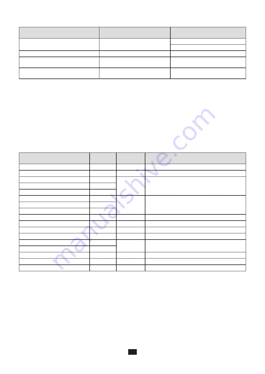
Specifications in DC
Quantity
Measurement range
Typical intrinsic uncertainty **
Voltage (V)
V = [10 V ; 1000 V]
± 1%R ± 3 V (PEL 102/103)
± 0.2%R ± 0.5 V (PEL 104)
Current (I) without current sensor *
I = [5% Inom ; 120% Inom]
± 1%R ± 0.3% Inom
Power (P)
kW
V = [100 V ; 1000 V]
I = [5% Inom ; 120% Inom]
± 1%R ± 0.3% Pnom
Energy (Ep)
kWh
V = [100 V ; 1000 V]
I = [5% Inom ; 120% Inom]
± 1.5%R
Table 9
Inom is the value of the measured current for a current sensor output of 1 V. See Table 23 for the nominal current values.
Pnom is the power for V = 1000 V and I = Inom.
*: The intrinsic uncertainty for input current (I) is specified for an isolated input voltage of 1 V = Inom. The intrinsic uncertainty
of the connected current sensor should be added to this intrinsic uncertainty to determine the total intrinsic uncertainty. In the
case of using sensors Amp
Flex
®
and Mini
Flex
®
, intrinsic uncertainty is given in Table 24.
The intrinsic uncertainty for neutral current is the maximum intrinsic uncertainty on I1, I2 and I3.
**: Indicative maximum value of the intrinsic uncertainty. Higher uncertainties can be noted, in particular with EMI.
6.2.3.4.
Phase order
Conditions for a correct phase order: current phase orders, voltage phase orders and current vs voltage phase order are correct.
Conditions of correct current phase order
Distribution system
Abbreviation Voltage phase
order
Comments
1-phase 2-wire
1P-2W
No
1-phase 3-wire
1P-3W
Yes
ϕ
(I2, I1) = 180° +/- 30°
3-phase 3-wire
∆
(2 current sensors)
3P-3W∆2
Yes
ϕ
(I1, I3) = 120° +/- 30°
No I2 current sensors
3-phase 3-wire Open
∆
(2 current sensors)
3P-3W02
3-phase 3-wire Y (2 current sensors)
3P-3WY2
3-phase 3-wire
∆
(3 current sensors)
3P-3W∆3
Yes
[
ϕ
(I1, I3),
ϕ
(I3, I2),
ϕ
(I2, I1)] = 120° +/- 30°
3-phase 3-wire Open
∆
(3 current sensors)
3P-3W03
3-phase 3-wire Y (3 current sensors)
3P-3WY3
3-phase 3-wire
∆
balanced
3P-3W∆B
No
3-phase 4-wire Y
3P-4WY
Yes
[
ϕ
(I1, I3),
ϕ
(I3, I2),
ϕ
(I2, I1)] = 120° +/- 30°
3-phase 4-wire Y balanced
3P-4WYB
No
3-phase 4-wire Y 2½
3P-4WY2
Yes
[
ϕ
(I1, I3),
ϕ
(I3, I2),
ϕ
(I2, I1)] = 120° +/- 30°
3-phase 4-wire
∆
3P-4W∆
Yes
[
ϕ
(I1, I3),
ϕ
(I3, I2),
ϕ
(I2, I1)] = 120° +/- 30°
3-phase 4-wire Open
∆
3P-4WO
DC 2-wire
DC-2W
No
DC 3-wire
DC-3W
No
DC 4-wire
DC-4W
No
Table 10
Summary of Contents for pel 102
Page 1: ...Power energy logger EN User s manual PEL 102 PEL 103 PEL 104 ...
Page 24: ...24 Aggregation period Date and time IP address scrolling Wi Fi address scrolling PEL104 ...
Page 36: ...36 Three phase 3 wire balanced 3P 3W b U12 U23 U31 f P Q S PF P Q S tan ϕ I1 I2 I3 ϕ I1 U12 ...
Page 38: ...38 Three phase 4 wire wye balanced 3P 4WYb I1 I2 I3 V1 V2 V3 VN U12 U23 U31 f P Q S tan ϕ ...
Page 39: ...39 DC 2 wire dC 2W DC 3 wire dC 3W P Q S PF ϕ I1 V1 P Q S tan ϕ P I V VN I1 I2 IN ...
Page 40: ...40 DC 4 wire dC 4W P I1 I2 I3 IN V1 V2 V3 VN V1 V2 VN ...
Page 48: ...48 Two phase 3 wire 1P 3W I1 I2 V1 V2 U12 VN P Q S P Q S ...
Page 51: ...51 P Q S ...
Page 85: ...85 ...


