60
6.2.3.5.
Temperature
For V, U, I, P, Q, S, PF, and E:
300 ppm/°C, with 5% < I < 120% and PF = 1
500 ppm/°C, with 10% < I < 120% and PF = 0.5 inductive
DC offset
V: 10 mv/°C typical
I: 30 ppm Inom /°C typical
6.2.3.6.
Common mode rejection
The common mode rejection ratio on neutral input is 140 dB typical.
For example, 110 V applied on the neutral input will add 11 μV on Amp
Flex
®
/MiniFlex
®
values which is a 230 mA error at 60 Hz.
110 V applied on the neutral input will add 11 μV on other current sensors values which is a 0,01% Inom additional error.
6.2.3.7.
Magnetic field influence
For current inputs to which MiniFlex
®
or AmpFlex
®
flexible current sensors are connected: 10 mA/A/m typically at 50/60 Hz.
6.2.4. CURRENT SENSORS
6.2.4.1.
Precautions for use
Refer to the safety sheet or user’s manual that was supplied with your current sensors.
Current clamps and flexible current sensors are used to measure the current flowing in a cable without opening the circuit. They
also insulate the user from dangerous voltages in the circuit.
The choice of current sensor to be used depends on the current to be measured and the diameter of the cables.
When installing current sensors, have the arrow on the probe or sensor point towards the load.
6.2.4.2.
Specifications
The measurement ranges are those of the sensors. In some cases, they may differ from the ranges that can be measured by the
PEL. Refer to the user manual distributed with the current sensor.
a) MiniFlex
®
MA193 or MiniFlex
®
MA194
The MiniFlex
®
Flexible Current Sensor can be used to measure the current in a cable without opening the circuit. It also serves to
isolate the user from hazardous voltages in the circuit. This sensor can only be used as an accessory of an instrument. If you have
several sensors, you can mark each of them before connecting it using one of the color-coded rings supplied with the instrument
to identify the phase. Then connect the sensor to the instrument.
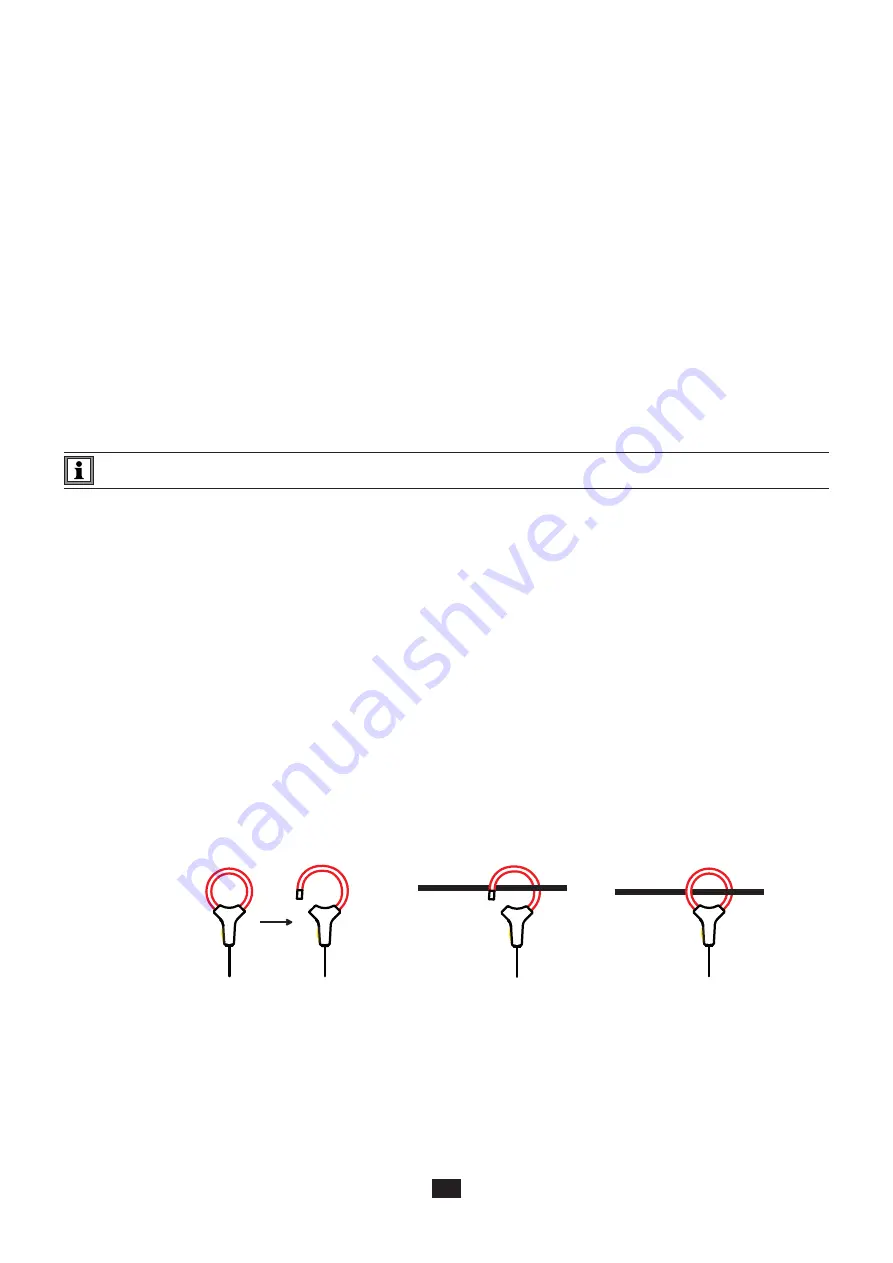
Press the yellow opening device to open the sensor. Then, place it around the conductor through which the current to be
measured flows (only one conductor per sensor).
Close the sensor. In order to optimize measurement quality, it is best to center the conductor in the sensor and make the shape
of the sensor as circular as possible.
To disconnect the sensor, open it and withdraw it from the conductor. Then disconnect the sensor from the instrument.
Summary of Contents for pel 102
Page 1: ...Power energy logger EN User s manual PEL 102 PEL 103 PEL 104 ...
Page 24: ...24 Aggregation period Date and time IP address scrolling Wi Fi address scrolling PEL104 ...
Page 36: ...36 Three phase 3 wire balanced 3P 3W b U12 U23 U31 f P Q S PF P Q S tan ϕ I1 I2 I3 ϕ I1 U12 ...
Page 38: ...38 Three phase 4 wire wye balanced 3P 4WYb I1 I2 I3 V1 V2 V3 VN U12 U23 U31 f P Q S tan ϕ ...
Page 39: ...39 DC 2 wire dC 2W DC 3 wire dC 3W P Q S PF ϕ I1 V1 P Q S tan ϕ P I V VN I1 I2 IN ...
Page 40: ...40 DC 4 wire dC 4W P I1 I2 I3 IN V1 V2 V3 VN V1 V2 VN ...
Page 48: ...48 Two phase 3 wire 1P 3W I1 I2 V1 V2 U12 VN P Q S P Q S ...
Page 51: ...51 P Q S ...
Page 85: ...85 ...


