66
AmpFlex
®
and MiniFlex
®
specifications
Sensor type
I nominal
Current
(RMS or DC)
Typical intrinsic
uncertainty
at 50/60 Hz
Intrinsic
uncertainty
at 400 Hz
Intrinsic
uncertainty on
ϕ
at
50/60 Hz
Typical
uncertainty
on
ϕ
at 400 Hz
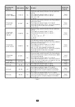
AmpFlex
®
A193
100 A
ac
[200 mA; 5 A[
± 1.2 % ± 50 mA
± 2 % ± 0,1 A
-
-
[5 A; 120 A[ *
± 1.2 % ± 50 mA
± 2 % ± 0,1 A
± 0.5°
- 0.5°
400 A
ac
[0,8 A; 20 A[
± 1.2 % ± 0.2 A
± 2 % ± 0,4 A
-
-
[20 A; 500 A[ *
± 1.2 % ± 0.2 A
± 2 % ± 0,4 A
± 0.5°
- 0.5°
2000 A
ac
[4 A; 100 A[
± 1.2 % ± 1 A
± 2 % ± 2 A
-
-
[100 A; 2400 A[ *
± 1.2 % ± 1 A
± 2 % ± 2 A
± 0.5°
- 0.5°
10,000 A
ac
[20 A; 500 A[
± 1.2 % ± 5 A
±2 % ± 10 A
-
-
[500 A; 12000 A[ *
± 1.2 % ± 5 A
± 2 % ± 10 A
± 0.5°
- 0.5°
MiniFlex
®
MA193
MA194
100 A
ac
[200 mA; 5 A[
± 1 % ± 50 mA
± 2 % ± 0,1 A
-
-
[5 A; 120 A[ *
± 1 % ± 50 mA
± 2 % ± 0,1 A
± 0.5°
- 0.5°
400 A
ac
[0,8 A; 20 A[
± 1 % ± 0.2 A
± 2 % ± 0,4 A
-
-
[20 A; 500 A[ *
± 1 % ± 0.2 A
± 2 % ± 0,4 A
± 0.5°
- 0.5°
2000 A
ac
[4 A; 100 A[
± 1 % ± 1 A
± 2 % ± 2 A
-
-
[100 A; 2,400 A[ *
± 1 % ± 1 A
± 2 % ± 2 A
± 0.5°
- 0.5°
10,000 A
ac
(MA194)
1
[20 A; 500 A[
± 1.2 % ± 5 A
± 2 % ± 10 A
-
-
[500 A; 12 000 A[ *
± 1.2 % ± 5 A
± 2 % ± 10 A
± 0,5°
- 0,5°
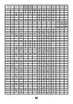
Table 24
1: Provided that the conductor can be clamped.
The nominal ranges are halved at 400Hz (*).
Limits of the AmpFlex
®
and
MiniFlex
®
Like all Rogowski probes, the AmpFlex
®
and
MiniFlex
®
deliver
output voltages
proportional to the frequency. A high current at a
high frequency can saturate the current inputs of the devices.
To avoid saturation, the following condition must be satisfied:
n=∞
n=1
[n. I
n
] < I
nom
∑
Where I
nom
is the range
of the current sensor
n is the order of the harmonic
I
n
is the current of the harmonic of order n
For example, the input current range of a dimmer must not exceed one fifth of the current range selected on the device.
This requirement does not take into account the limitation of the pass band of the device, which may lead to other errors.
Summary of Contents for pel 102
Page 1: ...Power energy logger EN User s manual PEL 102 PEL 103 PEL 104 ...
Page 24: ...24 Aggregation period Date and time IP address scrolling Wi Fi address scrolling PEL104 ...
Page 36: ...36 Three phase 3 wire balanced 3P 3W b U12 U23 U31 f P Q S PF P Q S tan ϕ I1 I2 I3 ϕ I1 U12 ...
Page 38: ...38 Three phase 4 wire wye balanced 3P 4WYb I1 I2 I3 V1 V2 V3 VN U12 U23 U31 f P Q S tan ϕ ...
Page 39: ...39 DC 2 wire dC 2W DC 3 wire dC 3W P Q S PF ϕ I1 V1 P Q S tan ϕ P I V VN I1 I2 IN ...
Page 40: ...40 DC 4 wire dC 4W P I1 I2 I3 IN V1 V2 V3 VN V1 V2 VN ...
Page 48: ...48 Two phase 3 wire 1P 3W I1 I2 V1 V2 U12 VN P Q S P Q S ...
Page 51: ...51 P Q S ...
Page 85: ...85 ...


