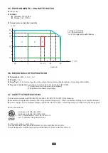
79
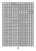
Distribution
network
Abbreviation
Phase
order
Remarks
Reference
diagram
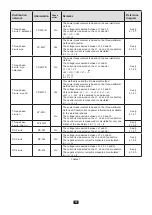
Three-phase,
3-wire
∆
, balanced
3P-3W
∆
B
No
The power measurement is based on the one-wattmeter
method.
The voltage is measured between L1 and L2.
The current is measured on the L3 conductor.
U
23
= U
31
= U
12
.
I
1
= I
2
= I
3
See §
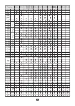
Three-phase
4-wire wye
3P-4WY
Yes
The power measurement is based on the three-wattmeter
method with neutral.
The voltage is measured between L1, L2 and L3.
The current is measured on the L1, L2 and L3 conductors.
The neutral current is measured or calculated:
i
N
= i
1
+ i
2
+ i
3
See §
Three-phase,
4-wire, wye,
balanced
3P-4WYB
No
The power measurement is based on the one-wattmeter
method.
The voltage is measured between L1 and N.
The current is measured on the L1 conductor.
V
1
= V
2
= V
3
U
23
= U
31
= U
12
= V
1
× √
3.
I
1
= I
2
= I
3
I
N
= 3 x I
1
See §
Three-phase,
3-wire, wye 2½
3P-4WY2
Yes
This method is called the 2½-element method
The power measurement is based on the three-wattmeter
method with a virtual neutral.
The voltage is measured between L1, L3 and N.
V2 is calculated: v
2
= - v
1
- v
3
, u1
2
= 2v
1
+ v
3
,
u
23
= - v
1
- 2v
3
. V
2
is assumed to be balanced.
The current is measured on the L1, L2 and L3 conductors.
The neutral current is measured or calculated:
i
N
= i
1
+ i
2
+ i
3
See §
Three-phase,
4-wire
∆
3P-4W
∆
No
The power measurement is based on the three-wattmeter
method with neutral, but no power information is available
for the individual phases.
The voltage is measured between L1, L2 and L3.
The current is measured on the L1, L2 and L3 conductors.
The neutral current is measured or calculated for only one
branch of the transformer: i
N
= i
1
+ i
2
+ i
3
See §
Three-phase,
4-wire, open
∆
3P-4WO
See §
DC 2-wire
DC-2W
No
The voltage is measured between L1 and N.
The current is measured on the L1 conductor.
See §
DC 3-wire
DC-3W
No
The voltage is measured between L1, L2 and N.
The current is measured on the L1 and L2 conductors.
The negative (return) current is measured or calculated:
i
N
= i
1
+ i
2
See §
DC 4-wire
DC-4W
No
The voltage is measured between L1, L2, L3 and N.
The current is measured on the L1, L2 and L3 conductors.
The negative (return) current is measured or calculated:
i
N
= i
1
+ i
2
+ i
3 .
See §
Table 27
Summary of Contents for pel 102
Page 1: ...Power energy logger EN User s manual PEL 102 PEL 103 PEL 104 ...
Page 24: ...24 Aggregation period Date and time IP address scrolling Wi Fi address scrolling PEL104 ...
Page 36: ...36 Three phase 3 wire balanced 3P 3W b U12 U23 U31 f P Q S PF P Q S tan ϕ I1 I2 I3 ϕ I1 U12 ...
Page 38: ...38 Three phase 4 wire wye balanced 3P 4WYb I1 I2 I3 V1 V2 V3 VN U12 U23 U31 f P Q S tan ϕ ...
Page 39: ...39 DC 2 wire dC 2W DC 3 wire dC 3W P Q S PF ϕ I1 V1 P Q S tan ϕ P I V VN I1 I2 IN ...
Page 40: ...40 DC 4 wire dC 4W P I1 I2 I3 IN V1 V2 V3 VN V1 V2 VN ...
Page 48: ...48 Two phase 3 wire 1P 3W I1 I2 V1 V2 U12 VN P Q S P Q S ...
Page 51: ...51 P Q S ...
Page 85: ...85 ...


