background image

Advanced Configuration 


Configuring Smart-1

     Page 26 


4.  If Multi-Domain Security Management is deployed, follow the same procedure to download the 

SmartDomain Manager. 

You have now completed the Smart-1 configuration.


To start working with your Smart-1 appliance as a Security Management Server refer to the 

Security 

Management Server Administration Guide

To start working with your Smart-1 appliance as Multi-Domain Security Management, refer to the 

Multi-

Domain Server Administration Guide


Advanced Configuration 

Advanced configuration can be done using the 

sysconfig 

or 

mdsconfig 

menu which can be accessed 

using the command line interface only. 


Note

 - The 

sysconfig 

menu is only available after running the 

First 

Time Configuration Wizard 

in the WebUI. 

Command line access can be obtained by console connection or through SSH. 


Connecting to the Smart-1 CLI 

You can connect to the command line interface of the Smart-1 appliance using: 


The provided serial console cable (DTE to DTE) and terminal emulation software such as 
HyperTerminal (from Windows) or Minicom (from Unix/Linux systems).  

Connection parameters for Smart-1 appliances are: 9600bps, no parity, 1 stop bit (8N1). 


An SSH connection to the management interface (if sshd is configured). 


Migration from Existing Provider-1 
Machines 

Smart-1 introduces a simple and easy to use tool that enables migration from existing NGX R65 and higher 
Provider-1 machines into the Smart-1 appliance. 

This script exports the entire existing MDS database into one .tgz file on the source machine that can be 
imported to the Smart-1 machine. 

To migrate from an existing NGX R65 and higher Provider-1 machine into the Smart-1 
appliance: 

Before starting the migration:


The exported configuration is approximately the size of the MDS installation. Therefore, before starting the 
migration make sure you have enough free disk space on the source and target machines. 

On the source machine:


1.  Get the 

p1_upgrade_tools.tgz

 package 

(

http://supportcontent.checkpoint.com/solutions?id=sk43266

)

2.  Extract the package contents 

3.  Run the export_mds.sh tool (make sure it has executable permissions) 

# export_mds.sh <path to store exported mds configuration>


On the Smart-1 appliance:


1.  Verify that no customers are defined, and that there are no global objects and policies on the Smart-1 

machine. Administrators and/or GUI clients will be overwritten. 

2.  Transfer the exported mds file to the 

/var

 partition on the Smart-1 machine.  

3.  Run the import tool: 

Summary of Contents for Smart-1 150

Page 1: ...23 February 2011 Getting Started Guide Smart 1 50 150 Models S 30 S 40 ...

Page 2: ...Check Point assumes no responsibility for errors or omissions This publication and features described herein are subject to change without notice RESTRICTED RIGHTS LEGEND Use duplication or disclosure by the government is subject to restrictions as set forth in subparagraph c 1 ii of the Rights in Technical Data and Computer Software clause at DFARS 252 227 7013 and FAR 52 227 19 TRADEMARKS Refer ...

Page 3: ...SmartEvent Server option available from R75 only Security Management Installation Type on page 21 Improved formatting and document layout 26 January 2011 Guide now applies to all Check Point software versions Added Rack mounting instructions Rack Mounting Smart 1 50 150 on page 12 Updated the First Time Configuration Wizard Instructions Using the First Time Configuration Wizard on page 19 26 augus...

Page 4: ...llowed to short The battery cell may heat up under these conditions and present a burn hazard Warning DANGER OF EXPLOSION IF BATTERY IS INCORRECTLY REPLACED REPLACE ONLY WITH SAME OR EQUIVALENT TYPE RECOMMENDED BY THE MANUFACTURER DISCARD USED BATTERIES ACCORDING TO THE MANUFACTURER S INSTRUCTIONS Disconnect the system board power supply from its power source before you connect or disconnect cable...

Page 5: ...bility to access information in that form Canadian Department Compliance Statement This Class A digital apparatus complies with Canadian ICES 003 Cet appareil numérique de la classe A est conforme à la norme NMB 003 du Canada Japan Class A Compliance Statement European Union EU Electromagnetic Compatibility Directive This product is herewith confirmed to comply with the requirements set out in the...

Page 6: ... First Time Configuration Wizard 19 Starting the First Time Configuration Wizard 19 Welcome 20 Appliance Date and Time Setup 20 Network Connections 21 Routing Table 21 DNS and Domain Settings 21 Management Settings 21 Multi Domain Security Management Settings 24 Installing the SmartConsole GUI Clients 25 Advanced Configuration 26 Connecting to the Smart 1 CLI 26 Migration from Existing Provider 1 ...

Page 7: ...troduction 41 Initial Login 41 Basic Configuration Options 42 Remotely Controlling the Appliance 42 Remotely Controlling the Power of the Appliance 42 Managing LOM Card Users 43 Configuring LOM Keyboard mouse Settings 43 Configuring LOM Settings 44 Setting the Date and Time 44 Defining a LOM Login Message 44 Registration and Support 45 Registration 45 Support 45 Where to From Here 45 ...

Page 8: ...come to the Check Point family We look forward to meeting all of your current and future network application and management security needs Smart 1 Overview Smart 1 appliances deliver Check Point s market leading security management software blades on a dedicated hardware platform specifically designed for mid size and large enterprise security networks Based upon Check Point s software blade archi...

Page 9: ...environment Instead they can focus on deploying resources on the important threats and trends that pose the greatest risk to their business You can configure Smart 1 as a Security Management server with SmartEvent In R75 and higher you can also configure Smart 1 as a dedicated server for SmartEvent Shipping Carton Contents Item Description Appliance A single Smart 1 appliance Rack Mounting Accesso...

Page 10: ...eports SmartReporter contains these components SmartReporter Client A GUI to generate define and display reports SmartReporter Server Contains reports report definitions and report schedules Log Consolidator Reads logs consolidates them according to the consolidation policy and adds them to the SmartReporter database Multi Domain Security Management Provider 1 Terminology The following terms relat...

Page 11: ...Name Starting with R75 Used in this Guide Multi domain server MDS Multi Domain Server Customer Domain Customer Management Add on CMA Domain Management Server Customer Log Module CLM Domain Log Server Multi Domain Log Module MLM Multi Domain Log Server ...

Page 12: ...ack cabinet review the following guidelines Make sure that the room air temperature is below 35 C 95 F Do not block any air vents Normally 15 cm 6 in of air space in the rear and 5 cm 2 in in the front provides proper airflow Install the appliances in the cabinet starting at the bottom and going up Install the heaviest appliance at the bottom of the rack cabinet Do not extend more than one device ...

Page 13: ... Smart 1 150 The distance from the center of any hole to the center of the third hole above it is equivalent to 1U The mounting holes in a standard 19 inch 482 6 mm server rack rail are arranged as follows When installing appliances start measuring from the center of the two holes with closer spacing Otherwise the screw holes on the appliance may not match those on the rack Rack Mounting Hardware ...

Page 14: ...1 50 6 Screws for Smart 1 150 6 32 6 6 Secures the appliance rail to Smart 1 150 Appliance bracket ear for Smart 1 50 2 Attaches to the Smart 1 50 front panel Both bracket ears are identical Screw for Smart 1 50 appliance bracket ear 6 Attaches the Smart 1 50 bracket ears to the appliance Handle for Smart 1 150 2 Attaches to the Smart 1 150 front panel Both handles are identical Screw for Smart 1 ...

Page 15: ...l the correct holes in the appliance rail line up with the holes in the side of the appliance On the Smart 1 50 line up the four holes marked 50 with the holes in the appliance On the Smart 1 150 line up the three holes marked 150 with the holes in the appliance 3 Attach the appliance rail to the side of the Smart 1 appliance For Smart 1 50 use four M3 6 screws For Smart 1 150 use three 6 32 6 scr...

Page 16: ...to one side of the appliance For Smart 1 50 use three screws For Smart 1 150 use two screws 2 Repeat for the other side of the appliance Attaching the Mounting Brackets to the Rack Attach the mounting brackets to the rack 1 While standing in the front of the rack place a mounting bracket in position on one side of the rack 2 Attach the mounting bracket to the rack vertical rail at the front using ...

Page 17: ...nt of the rack 6 Tighten the two screws that attach the mounting bracket to the rack vertical rail 7 Repeat for the other side of the rack Attach the mounting bracket to the other side of the rack Installing Smart 1 50 150 In the Rack Carefully install the Smart 1 50 150 in the rack Important The Smart 1 appliance is very heavy To lift and install it Two people are required for Smart 1 50 Three pe...

Page 18: ...ack Mounting Smart 1 50 150 Page 18 1 Line up the appliance rail on the appliance with the mounting bracket rails 2 Carefully slide the appliance into the mounting bracket rails 3 Push the appliance in until the appliance locks in the rails ...

Page 19: ...y If you hear the alarm check that all power supplies are connected to the outlets If needed replace the faulty power supply immediately and connect the new unit to the A C outlet See Removing the Power Supply on page 35 Using the First Time Configuration Wizard Perform the initial configuration of Smart 1 using the First Time Configuration Wizard At any time you can click Quit to exit the wizard ...

Page 20: ...tration IP address https 192 168 1 1 4434 Note Pop ups must always be allowed on https appliance_ip_address The login page appears 4 Log in with the default system administrator login name password admin admin and click Login 5 The First Time Configuration Wizard runs The Wizard presents a number of windows in which you are prompted to configure Smart 1 Note The features configured in the wizard a...

Page 21: ...the Routing Table page DNS and Domain Settings Set the Host Domain and DNS Servers in the DNS and Domain Settings page The host name must start with a letter and cannot be named Com1 Com2 Com9 Management Settings The remaining screens of the First Time Configuration Wizard are specific to the image you have on the Smart 1 If Smart 1 has a Security Management server image continue with the screens ...

Page 22: ...ose to install a Security Management server in the Security Management page Primary Security Management is the Security Management server that will normally be active To set up a Security Management server in a non Management HA deployment choose this option In a Management HA deployment if the Primary Security Management server fails the Secondary Security Management server takes over Secondary S...

Page 23: ...ing to Hostname or IP address Enter Any to manage Smart 1 from anywhere Note It is not recommended to use the Any value for security reasons Additional options are available via the WebUI menu after you complete the First Time Configuration Wizard Secure Internal Communication In the Secure Internal Communication page enter a SIC Activation Key and remember it as you will enter it again when confi...

Page 24: ...the Any value for security reasons Additional options are available via the WebUI menu after you complete the First Time Configuration Wizard Multi Domain Security Management Installation Type c Multi Domain Server select this option if you want the appliance to house Multi Domain Security Management system information including details of the Multi Domain Security Management deployment its admini...

Page 25: ...martConsole Applications Configuring a security policy requires you to install the SmartConsole applications In the Download SmartConsole Applications window you can download SmartConsole and install it on Windows machines For a detailed list of supported Windows operating systems for SmartConsole refer to the release notes of your Check Point version in the Check Point Support Center http support...

Page 26: ...s are 9600bps no parity 1 stop bit 8N1 An SSH connection to the management interface if sshd is configured Migration from Existing Provider 1 Machines Smart 1 introduces a simple and easy to use tool that enables migration from existing NGX R65 and higher Provider 1 machines into the Smart 1 appliance This script exports the entire existing MDS database into one tgz file on the source machine that...

Page 27: ... 1 Machines Configuring Smart 1 Page 27 MDS_SYSTEM install mds_import sh full path to the imported configuration 4 Start the mds Note that the first start up of the mds after import takes considerably longer than subsequent start ups ...

Page 28: ... entered automatically if the SmartEvent version is newer than the version of the Security Management Server If so select the most recent version available from the Version drop down list d In the Management Software Blades list select the blades that are installed on the new host 3 Install the database on all log servers from which SmartEvent reads data select Policy Install Database and select t...

Page 29: ...add all the CMAs with which you will be working 2 Objects will be synchronized from the CMAs The synchronization progress can be monitored from the status window in the Overview pane Configuring the SmartEvent Clients You must perform these configurations to make the components of the SmartEvent functional After you have accomplished the tasks for SmartEvent Intro events will begin to appear in th...

Page 30: ...vironment the Consolidation session is automatically created If there is more than one log server you must create the Consolidation session for each log server To create a Consolidation session 1 In the Selection Bar view select Management Consolidation 2 Select the Sessions tab 3 Click Create New to create a new session The New Consolidation Session window appears 4 Select the log server from whi...

Page 31: ...are This chapter provides instructions for installing and removing hardware components on the Smart 1 appliance In This Chapter Smart 1 50 Front Panel 32 Smart 1 150 Front panel 33 LCD Display Screen 33 Customer Replaceable Parts 34 ...

Page 32: ...ort for a serial connection to the appliance using a terminal emulation program such as HyperTerminal 5 LOM Lights out Management port 6 Management configuration port 7 Built in ethernet ports Lan1 Lan3 8 slot for optional fiber channel SAN card For setup instructions see sk43364 http supportcontent checkpoint com solutions id sk43364 9 4 hard disk drives ...

Page 33: ...up instructions see sk43364 http supportcontent checkpoint com solutions id sk43364 7 12 hard disk drives 8 LCD display screen 9 Screen operation keys LCD Display Screen Smart 1 appliances other than Smart 1 25 have an LCD screen that can be used to perform basic management operations The management IP address netmask and default gateway of the Check Point appliance can be configured The appliance...

Page 34: ...rent digit or Customer Replaceable Parts To ensure maximum availability and ease of maintenance the Smart 1 appliance contains the following customer replaceable parts Smart 1 50 Two power supplies Four hard disk drives Two cooling fans Smart 1 150 Three power supplies Up to twelve hard disk drives Three cooling fans Unless directed to do so by Check Point technical support customers are prohibite...

Page 35: ...in up to 12 hot swappable hard disk drives Implemented by a dedicated LSI Logic RAID controller Smart 1 performs RAID10 mirroring and striping across all of the installed hard disk drives Use the raidconfig SecurePlatform command to perform basic maintenance and monitoring procedures on your Smart 1 RAID array raidconfig Description Perform basic maintenance and monitoring procedures on the Smart ...

Page 36: ...to initiate the rebuild of the RAID array on the new disk drive Smart 1 150 Raid Storage Smart 1 150 can contain up to 12 hard drives If the appliance has been purchased with less than 12 hard drives and you would like to add more storage capacity follow the guidelines and instructions below RAID Storage Guidelines Additional hard drives should always be added in multiples of four the appliance sh...

Page 37: ...us of the hard disk drives Additional hard disk drives should appear configured in additional four discs RAID 10 arrays 2 Run the lvdisplay dev vg_splat lv_log command The additional storage should appear available under this logical volume Cooling Fans The Smart 1 appliance contains three cooling fans Each cooling fan operates independently of the other s providing redundancy in the event of fail...

Page 38: ...n you wish to restore 3 Click Revert Restoring Factory Defaults using the Console The below procedure defines how to restore factory defaults using a terminal emulation program such as HyperTerminal 1 Using the supplied serial console cable to the console port connect Smart 1 to a HyperTerminal machine In the Port Settings window the setting for the Serial console is 9600 8N1 9600 BPS 8 bits no pa...

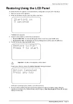
Page 39: ...Security Management Server and then press the UP arrow Reset to PV 1 FCD for Multi Domain Security Management and then press the UP arrow 4 Confirm the reset by pressing the UP arrow Important All data on the appliance will be erased Pressing any other key causes the Action Canceled message to appear At this point pressing any key returns you to the boot menu 5 Once you have confirmed the reset wa...

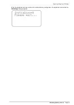
Page 40: ...Restoring Using the LCD Panel Restoring Factory Defaults Page 40 When the appliance has been restored to its default factory configuration the appliance reboots and the Initializing message appears ...

Page 41: ...to remotely administer the appliance and perform maintenance operations The LOM card is configured by connecting to the LOM port through a Web interface The basic configuration options of the LOM card are Appliance Control Remote lights out power management Turning the power ON or OFF or resetting the appliance LOM User Management Managing LOM card user accounts LOM Settings Managing LOM IP settin...

Page 42: ...ing this option ensure that you have Java Runtime installed on the host machine To run the remote console 1 Click the Appliance Control menu option 2 Select KVM Console and then Open Console A new window opens that enables you to remotely control the Smart 1 appliance Remotely Controlling the Power of the Appliance Using the LOM card it is possible to remotely switch ON the Smart 1 appliance even ...

Page 43: ...ogin Yes Yes Enter KVM console Yes Yes Create user Yes N A Modify user Yes N A Delete user Yes N A Date time settings Yes Yes Edit login message Yes N A Remote power management Yes Yes Network setting Yes N A Keyboard mouse setting Yes Yes To modify a user 1 Select an existing user from the list and click Modify The User Modify dialog box appears 2 Modify the fields as required 3 To change the pas...

Page 44: ...s of the LOM Subnet mask the subnet mask of the LOM s local network Gateway IP address the Default Gateway IP address Remote Console and HTTPS port port number on which the device s Remote Console server and HTTPS server are listening Setting the Date and Time This option enables you to manually change the date and time of the LOM card Defining a LOM Login Message This option enables you to define...

Page 45: ...cal information about Check Point products consult the Check Point Support Center http supportcenter checkpoint com Where to From Here You have now learned the basics that you need to get started The next step is to obtain more advanced knowledge of your Check Point software See the relevant documentation for your software version on the Check Point Support Center Check Point documentation is avai...

Reviews: