154
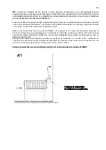
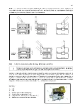
Ejemplo esquemático de una instalación de la B11 tipo válido para los modelos de FLAME 4 y FLAME
6 de FLAME 9.
Para instalar B21, esclavizado bajo el capó, no sirve cualquier tramo de la tubería vertical y no está obligado a
romper el dispositivo que se utiliza para dibujar el horno hornos FLAME 9. Hornos FLAME 4 y FLAME 6 ya han
integrado en el dispositivo de ruptura proyecto tubo de escape y no debe ser eliminado.
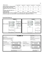
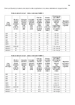
PARÁMETROS DE LA CHIMENEA / CHIMNEY PARAMETERS
Flame 4 oven
Gas G30
Gas G20
Gas G25
Gas G25.1
Gas G25.3
Presión humo de la chimenea [Pa]
Chimney smoke pressure [Pa]
-2.0
-1,8
-2,1
-2,1
-2.2
Temperatura humo de la chimenea
[ºC]
Chimney smoke temperature [°C]
127
135
132
132
134
Fuerza humo
[g/s]
Smoke mass [g/s]
41,00
39,52
41,42
42,72
37.61
Valores para un único horno, recogidos con un tubo vertical de 1 metro y de diámetro Ø 150 mm
Values for a single oven, collected with a 1-metre vertical tube with a diameter (Ø) of 150 mm.
Flame 6 oven
Gas G30
Gas G20
Gas G25
Gas G25.1
Gas G25.3
Presión humo de la chimenea [Pa]
Chimney smoke pressure [Pa]
-2,4
-2,4
-2,5
-2,4
-2.2
Temperatura humo de la chimenea
[ºC]
Chimney smoke temperature [°C]
125,0
128,0
120,0
124,0
126,0
Fuerza humo
[g/s]
Smoke mass [g/s]
40,99
38,80
40,98
42,02
36.56
Valores para un único horno, recogidos con un tubo vertical de 1 metro y de diámetro Ø 150 mm
Values for a single oven, collected with a 1-metre vertical tube with a diameter (Ø) of 150 mm.
Summary of Contents for CHFPG4
Page 2: ...2...
Page 14: ...14 3 3 Schemi elettrici...
Page 15: ...15...
Page 47: ...47 3 3 Sch mas de c blage...
Page 48: ...48...
Page 80: ...80 3 3 Wiring diagrams...
Page 81: ...81...
Page 102: ...102 RU Category II2H3 Type of installation FLAME4 A1 B11 B21 FLAME 6 9 B11 B21...
Page 104: ...104 7 6 131 7 7 132 8 132 8 1 132 8 2 132 8 2 1 132 8 2 2 132 8 3 132 9 133 10 134...
Page 105: ...105 1 1 1 m 1 2 m 1 3 1 4...
Page 108: ...108 1 11 1 12 1 13 CE CE...
Page 109: ...109 RU 1 14 2 2 1...
Page 110: ...110 2 2 2 3...
Page 112: ...112 FLAME 9 148 126 47 105 105 15 196 18 220 230 50 60 50 3 x 0 75 2 B11 B21 I...
Page 113: ...113 3 3...
Page 114: ...114...
Page 116: ...116 4 25 50 50 m 5 5 1...
Page 117: ...117 5 2 25 50 50 6 6 1 4 2 F 6 2 6 2 1 3...
Page 118: ...118 6 2 1 1 6 2 2 1 13 1 5 6 2 3 A1 B11...
Page 119: ...119 B21 FLAME 4 FLAME 6 FLAME 9 B11 B11 A1 FLAME 4...
Page 123: ...123 FLAME 4 FLAME 6 45 6 2 4 6 3 1 EV1 2 EV2 3 Pin 4 Pout 5 6...
Page 124: ...124 1 0 1 E 2 3 Pin 6 7 3 Pin 3 4 Pout 4 B MAX 10 5 B MIN C D 6x1 E...
Page 130: ...130 A B C D E F G H 7 2 200 C 1 8 300 350 C 7 3 200 C A 1 D B 0 B 1 7 4...
Page 131: ...131 7 5 380 C 3 3 5 1 30 40 380 2 3 4 5 B 0 B 1 20 7 6 H 1...
Page 132: ...132 7 7 D 0 A 0 8 8 1 89 391 8 2 8 2 1 350 60 100 C 8 2 2 8 3...
Page 133: ...133 9 0 1 1 PF Schuko...
Page 134: ...134 10 13 151 25 2005 2002 95 2002 96 2003 108...
Page 146: ...146 3 3 Esquemas el ctricos...
Page 147: ...147...
Page 179: ...179 3 3 Schaltpl ne...
Page 180: ...180...
Page 201: ...201 EXPLODED VIEW DRAWINGS AND SPARE PARTS...
Page 202: ...202...
Page 203: ...203...
Page 209: ...209 ROTATING DOOR SYSTEM LAMP SYSTEM...
Page 210: ...210 ANALOGUE THERMOMETER CONTROLS DIGITAL THERMOMETER CONTROLS...
Page 211: ...211...

