16
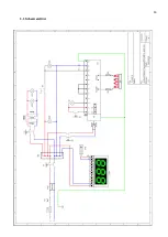
Legenda - Legend
Symbol
Descrizione
Description
L
Linea di Fase
Phase line
N
Linea di Neutro
Neutral line
FAD
Filtro EMC
EMC filter
TS
Termostato di sicurezza a riarmo manuale
Manual reset safety thermostat
IG
Interruttore generale
Main switch
MD
Morsettiera
Branching terminal board
IL
Interruttore luce
Chamber light switch
TRS
Trasformatore
Transformer
LDX-LSX
Luci camera
Chamber light
SAP
Spia presenza tensione
Electric power supply indicator light
FU
Fusibile (2A)
Card protection fuse (5A)
TR
Termostato di regolazione
Temperature regulation thermostat
STR
Spia temperatura
Temperature reached indicator light
IM
Interruttore Stand-by
Stand-by switch
IR
Pulsante di riarmo
Gas reset button
SR
Spia mancata accensione
Flame failure alarm indicator light
VG
Elettrovalvola
Electrical valve
SG
Dispositivo elettronico
Electronic control unit
EA
Elettrodo di accensione
Ignition electrodes
ER
Elettrodo di rilevazione
Detection electrode
BG
Bruciatore
Gas burner
DSP
Termometro digitale
(se
presente nell’impianto elettrico)
Digital thermometer display
(if present on the electrical system)
STD
Sonda termometro
(se presente nell’impianto elettrico)
Digital thermometer probe
(if present on the electrical system)
Summary of Contents for CHFPG4
Page 2: ...2...
Page 14: ...14 3 3 Schemi elettrici...
Page 15: ...15...
Page 47: ...47 3 3 Sch mas de c blage...
Page 48: ...48...
Page 80: ...80 3 3 Wiring diagrams...
Page 81: ...81...
Page 102: ...102 RU Category II2H3 Type of installation FLAME4 A1 B11 B21 FLAME 6 9 B11 B21...
Page 104: ...104 7 6 131 7 7 132 8 132 8 1 132 8 2 132 8 2 1 132 8 2 2 132 8 3 132 9 133 10 134...
Page 105: ...105 1 1 1 m 1 2 m 1 3 1 4...
Page 108: ...108 1 11 1 12 1 13 CE CE...
Page 109: ...109 RU 1 14 2 2 1...
Page 110: ...110 2 2 2 3...
Page 112: ...112 FLAME 9 148 126 47 105 105 15 196 18 220 230 50 60 50 3 x 0 75 2 B11 B21 I...
Page 113: ...113 3 3...
Page 114: ...114...
Page 116: ...116 4 25 50 50 m 5 5 1...
Page 117: ...117 5 2 25 50 50 6 6 1 4 2 F 6 2 6 2 1 3...
Page 118: ...118 6 2 1 1 6 2 2 1 13 1 5 6 2 3 A1 B11...
Page 119: ...119 B21 FLAME 4 FLAME 6 FLAME 9 B11 B11 A1 FLAME 4...
Page 123: ...123 FLAME 4 FLAME 6 45 6 2 4 6 3 1 EV1 2 EV2 3 Pin 4 Pout 5 6...
Page 124: ...124 1 0 1 E 2 3 Pin 6 7 3 Pin 3 4 Pout 4 B MAX 10 5 B MIN C D 6x1 E...
Page 130: ...130 A B C D E F G H 7 2 200 C 1 8 300 350 C 7 3 200 C A 1 D B 0 B 1 7 4...
Page 131: ...131 7 5 380 C 3 3 5 1 30 40 380 2 3 4 5 B 0 B 1 20 7 6 H 1...
Page 132: ...132 7 7 D 0 A 0 8 8 1 89 391 8 2 8 2 1 350 60 100 C 8 2 2 8 3...
Page 133: ...133 9 0 1 1 PF Schuko...
Page 134: ...134 10 13 151 25 2005 2002 95 2002 96 2003 108...
Page 146: ...146 3 3 Esquemas el ctricos...
Page 147: ...147...
Page 179: ...179 3 3 Schaltpl ne...
Page 180: ...180...
Page 201: ...201 EXPLODED VIEW DRAWINGS AND SPARE PARTS...
Page 202: ...202...
Page 203: ...203...
Page 209: ...209 ROTATING DOOR SYSTEM LAMP SYSTEM...
Page 210: ...210 ANALOGUE THERMOMETER CONTROLS DIGITAL THERMOMETER CONTROLS...
Page 211: ...211...


