73
The equipment that is already available on the market, with the relative technical documentation, will not be
considered incomplete or inappropriate due to possible subsequent modifications, adjustments or application of
new technologies on newly marketed machines.
The information in this manual only applies for models in the II2H3+ category and that are used in Italy. If used
in another European country with a different category, the manual must be translated with the references (setup
for the gas and local installation regulations) for the country of destination. The data plate on each appliance
indicates the codes for the European countries where the appliance may be sold and installed.
1.6 OVERVIEW
Information:
If exchanging information with the equipment Manufacturer or the Dealer, please refer to the serial number and
the identification data of the machine reported on the plate.
Liability:
With delivery of this manual, the Manufacturer declines any and all liability, both civil and criminal, for accidents
deriving from partial or total non-adherence to the specifications contained herein.
The Manufacturer also declines all liability for improper or incorrect use of the equipment, for unauthorized
modifications and/or repairs, as well as for use of non-original or spare parts not appropriate for these models.
m
Modifications and/or tampering with any functional part or component of the appliance may be
dangerous and cause damage to people and/or property.
For the reasons indicated above, it is strictly prohibited to tamper with the parts sealed by the
manufacturer. The manufacturer is not responsible for the consequences resulting from
improper use of the appliance. Its incorrect use invalidates the warranty with immediate effect.
Extraordinary maintenance:
Extraordinary maintenance operations must be performed by qualified personnel trained to work on the rolling
machine referred to in this manual.
It is advisable to stipulate a maintenance contract which includes checks to be performed at prefixed intervals.
It is particularly desirable to control at least annually of the exhaust pipe for installation Type B11 and B21
(chimney cleaning and verification efficiency fume hoods removal).
Responsibility for installation operations:
The Manufacturer shall not be responsible for the equipment installation operations. This is, and
remains, the responsibility of the installer who is in charge of executing the controls related to
the correctness of the proposed installation. In addition, all safety regulations foreseen by the
current laws in force in the state in which the machine is installed must be respected.
Use:
In addition to the instructions contained in this manual, the use of the machine is subject to all safety regulations
outlined in the specific laws in the Country where the machine is installed.
1.7 MAIN REGULATIONS AND DIRECTIVES THAT ARE RESPECTED AND MUST BE RESPECTED
Regulation 2016/426/EU of 9 March 2016 “on appliances burning gaseous fuels and repealing Directive
2009/142/EC;
Standards EN 203-1, EN 203-2-2 and EN 203-
3 concerning “Appliances for professional gas
-heated
kitchens”;
Standard EN 437: Gas test - Pressure test - Appliance categories;
Directive 2014/35/EC “on the harmonisation of the laws of Member States relating to electrical
e
quipment designed for use within certain voltage limits and repealing Directive 2006/95/EC”;
Directive 2014/30/EU “on the harmonisation of the laws of Member States relating to electromagnetic
compatibility and repealing Directive 2004/108/EC”;
Directive 8
9/391/EEC “on the introduction of measures to encourage improvements in the safety and
health of workers at work”;
Directive 2006/42/EC “on machinery and amending Directive 95/16/EC”;
Summary of Contents for CHFPG4
Page 2: ...2...
Page 14: ...14 3 3 Schemi elettrici...
Page 15: ...15...
Page 47: ...47 3 3 Sch mas de c blage...
Page 48: ...48...
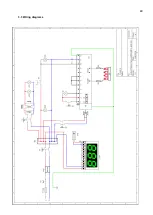
Page 80: ...80 3 3 Wiring diagrams...
Page 81: ...81...
Page 102: ...102 RU Category II2H3 Type of installation FLAME4 A1 B11 B21 FLAME 6 9 B11 B21...
Page 104: ...104 7 6 131 7 7 132 8 132 8 1 132 8 2 132 8 2 1 132 8 2 2 132 8 3 132 9 133 10 134...
Page 105: ...105 1 1 1 m 1 2 m 1 3 1 4...
Page 108: ...108 1 11 1 12 1 13 CE CE...
Page 109: ...109 RU 1 14 2 2 1...
Page 110: ...110 2 2 2 3...
Page 112: ...112 FLAME 9 148 126 47 105 105 15 196 18 220 230 50 60 50 3 x 0 75 2 B11 B21 I...
Page 113: ...113 3 3...
Page 114: ...114...
Page 116: ...116 4 25 50 50 m 5 5 1...
Page 117: ...117 5 2 25 50 50 6 6 1 4 2 F 6 2 6 2 1 3...
Page 118: ...118 6 2 1 1 6 2 2 1 13 1 5 6 2 3 A1 B11...
Page 119: ...119 B21 FLAME 4 FLAME 6 FLAME 9 B11 B11 A1 FLAME 4...
Page 123: ...123 FLAME 4 FLAME 6 45 6 2 4 6 3 1 EV1 2 EV2 3 Pin 4 Pout 5 6...
Page 124: ...124 1 0 1 E 2 3 Pin 6 7 3 Pin 3 4 Pout 4 B MAX 10 5 B MIN C D 6x1 E...
Page 130: ...130 A B C D E F G H 7 2 200 C 1 8 300 350 C 7 3 200 C A 1 D B 0 B 1 7 4...
Page 131: ...131 7 5 380 C 3 3 5 1 30 40 380 2 3 4 5 B 0 B 1 20 7 6 H 1...
Page 132: ...132 7 7 D 0 A 0 8 8 1 89 391 8 2 8 2 1 350 60 100 C 8 2 2 8 3...
Page 133: ...133 9 0 1 1 PF Schuko...
Page 134: ...134 10 13 151 25 2005 2002 95 2002 96 2003 108...
Page 146: ...146 3 3 Esquemas el ctricos...
Page 147: ...147...
Page 179: ...179 3 3 Schaltpl ne...
Page 180: ...180...
Page 201: ...201 EXPLODED VIEW DRAWINGS AND SPARE PARTS...
Page 202: ...202...
Page 203: ...203...
Page 209: ...209 ROTATING DOOR SYSTEM LAMP SYSTEM...
Page 210: ...210 ANALOGUE THERMOMETER CONTROLS DIGITAL THERMOMETER CONTROLS...
Page 211: ...211...

