75
If the Gas type configuration is changed, replace
this wording, using the adhesive labels supplied by
the manufacturer.
1.12
SPARE PARTS
Use only original spare parts.
Do not wait until components are worn out before replacing them.
Replacing a worn component before breakage helps to prevent injuries deriving from accidents caused by
unexpected component breakage, which could provoke serious damage to persons or property.
Perform the periodical maintenance controls as indicated in the chapter "MAINTENANCE AND
CLEANING".
1.13
IDENTIFICATION PLATE
The plate on the equipment contains all relevant data, including Manufacturer data, the
serial number
and the
CE
conformity to type marking.
The
CE
marking is issued by a notified body following certification tests and the surveillance activities for the
product as foreseen by the regulation.
The plate also contains the data with
the gas setup, the European countries where it is sold with the relative
categories and nominal pressures.
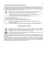
The following plate is also located on the appliance, which contains the main safety warnings.
EN
The appliance must be connected according to the current regulations and only used in well
ventilated rooms. Pay particular attention to the user and maintenance instructions before
operating it.
!
The plates must never be removed (the setup can be updated if converted to another gas type)
Summary of Contents for CHFPG4
Page 2: ...2...
Page 14: ...14 3 3 Schemi elettrici...
Page 15: ...15...
Page 47: ...47 3 3 Sch mas de c blage...
Page 48: ...48...
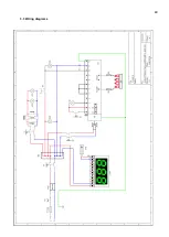
Page 80: ...80 3 3 Wiring diagrams...
Page 81: ...81...
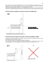
Page 102: ...102 RU Category II2H3 Type of installation FLAME4 A1 B11 B21 FLAME 6 9 B11 B21...
Page 104: ...104 7 6 131 7 7 132 8 132 8 1 132 8 2 132 8 2 1 132 8 2 2 132 8 3 132 9 133 10 134...
Page 105: ...105 1 1 1 m 1 2 m 1 3 1 4...
Page 108: ...108 1 11 1 12 1 13 CE CE...
Page 109: ...109 RU 1 14 2 2 1...
Page 110: ...110 2 2 2 3...
Page 112: ...112 FLAME 9 148 126 47 105 105 15 196 18 220 230 50 60 50 3 x 0 75 2 B11 B21 I...
Page 113: ...113 3 3...
Page 114: ...114...
Page 116: ...116 4 25 50 50 m 5 5 1...
Page 117: ...117 5 2 25 50 50 6 6 1 4 2 F 6 2 6 2 1 3...
Page 118: ...118 6 2 1 1 6 2 2 1 13 1 5 6 2 3 A1 B11...
Page 119: ...119 B21 FLAME 4 FLAME 6 FLAME 9 B11 B11 A1 FLAME 4...
Page 123: ...123 FLAME 4 FLAME 6 45 6 2 4 6 3 1 EV1 2 EV2 3 Pin 4 Pout 5 6...
Page 124: ...124 1 0 1 E 2 3 Pin 6 7 3 Pin 3 4 Pout 4 B MAX 10 5 B MIN C D 6x1 E...
Page 130: ...130 A B C D E F G H 7 2 200 C 1 8 300 350 C 7 3 200 C A 1 D B 0 B 1 7 4...
Page 131: ...131 7 5 380 C 3 3 5 1 30 40 380 2 3 4 5 B 0 B 1 20 7 6 H 1...
Page 132: ...132 7 7 D 0 A 0 8 8 1 89 391 8 2 8 2 1 350 60 100 C 8 2 2 8 3...
Page 133: ...133 9 0 1 1 PF Schuko...
Page 134: ...134 10 13 151 25 2005 2002 95 2002 96 2003 108...
Page 146: ...146 3 3 Esquemas el ctricos...
Page 147: ...147...
Page 179: ...179 3 3 Schaltpl ne...
Page 180: ...180...
Page 201: ...201 EXPLODED VIEW DRAWINGS AND SPARE PARTS...
Page 202: ...202...
Page 203: ...203...
Page 209: ...209 ROTATING DOOR SYSTEM LAMP SYSTEM...
Page 210: ...210 ANALOGUE THERMOMETER CONTROLS DIGITAL THERMOMETER CONTROLS...
Page 211: ...211...


