78
3. GENERAL SPECIFICATIONS
3.1 Features
The gas pizza oven is for professional use only and its external panels with specific slots and ventilation holes,
are made of painted iron. The oven is equipped with a cooking chamber featuring refractory plates that can
receive from four to nine standard pizzas at the same time, depending on the model. The cooking chamber is
heated by an atmospheric burner fixed under the plates.
The cooking temperature is programmed by the control
thermostat on the control panel and is displayed by the digital thermometer on the top. The gas supply is
regulated by the solenoid valve that supplies the burner with on/off cycles. The presence of the flame is
registered by a detection electrode connected to the circuit board.
If there is an ignition failure or absence of gas, the burner reset button must be activated and the causes that
led to the block must be rectified. The oven must be installed perfectly level in a good-sized, well-ventilated
room.
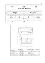
3.2 Technical data
F
L
AME
4
External dimensions (cm)
Width
Depth
Height
113
91
47
Cooking chamber dimensions (cm)
Width
Depth
Height
70
70
15
Weight (kg)
Ø FLUE GAS (cm)
132
15
ELECTRIC DATA
Supply voltage
(V)
Frequency
(Hz)
Maximum power absorbed
(W)
Power cable
220-230
50/60
50
3 x 0.75 mm
2
Other data
Gas connection fitting
Type of gas installation
Electrical safety class
½”
A
1
- B
11
-
B
21
I
F
L
AME
6
External dimensions (cm)
Width
Depth
Height
113
126
47
Cooking chamber dimensions (cm)
Width
Depth
Height
70
105
15
Weight (kg)
Ø FLUE GAS (cm)
164
15
ELECTRIC DATA
Supply voltage
(V)
Frequency
(Hz)
Maximum power absorbed
(W)
Power cable
220-230
50/60
50
3 x 0.75 mm
2
Other data
Gas connection fitting
Gas connection fitting
Gas connection fitting
½”
B
11
-
B
21
I
Summary of Contents for CHFPG4
Page 2: ...2...
Page 14: ...14 3 3 Schemi elettrici...
Page 15: ...15...
Page 47: ...47 3 3 Sch mas de c blage...
Page 48: ...48...
Page 80: ...80 3 3 Wiring diagrams...
Page 81: ...81...
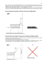
Page 102: ...102 RU Category II2H3 Type of installation FLAME4 A1 B11 B21 FLAME 6 9 B11 B21...
Page 104: ...104 7 6 131 7 7 132 8 132 8 1 132 8 2 132 8 2 1 132 8 2 2 132 8 3 132 9 133 10 134...
Page 105: ...105 1 1 1 m 1 2 m 1 3 1 4...
Page 108: ...108 1 11 1 12 1 13 CE CE...
Page 109: ...109 RU 1 14 2 2 1...
Page 110: ...110 2 2 2 3...
Page 112: ...112 FLAME 9 148 126 47 105 105 15 196 18 220 230 50 60 50 3 x 0 75 2 B11 B21 I...
Page 113: ...113 3 3...
Page 114: ...114...
Page 116: ...116 4 25 50 50 m 5 5 1...
Page 117: ...117 5 2 25 50 50 6 6 1 4 2 F 6 2 6 2 1 3...
Page 118: ...118 6 2 1 1 6 2 2 1 13 1 5 6 2 3 A1 B11...
Page 119: ...119 B21 FLAME 4 FLAME 6 FLAME 9 B11 B11 A1 FLAME 4...
Page 123: ...123 FLAME 4 FLAME 6 45 6 2 4 6 3 1 EV1 2 EV2 3 Pin 4 Pout 5 6...
Page 124: ...124 1 0 1 E 2 3 Pin 6 7 3 Pin 3 4 Pout 4 B MAX 10 5 B MIN C D 6x1 E...
Page 130: ...130 A B C D E F G H 7 2 200 C 1 8 300 350 C 7 3 200 C A 1 D B 0 B 1 7 4...
Page 131: ...131 7 5 380 C 3 3 5 1 30 40 380 2 3 4 5 B 0 B 1 20 7 6 H 1...
Page 132: ...132 7 7 D 0 A 0 8 8 1 89 391 8 2 8 2 1 350 60 100 C 8 2 2 8 3...
Page 133: ...133 9 0 1 1 PF Schuko...
Page 134: ...134 10 13 151 25 2005 2002 95 2002 96 2003 108...
Page 146: ...146 3 3 Esquemas el ctricos...
Page 147: ...147...
Page 179: ...179 3 3 Schaltpl ne...
Page 180: ...180...
Page 201: ...201 EXPLODED VIEW DRAWINGS AND SPARE PARTS...
Page 202: ...202...
Page 203: ...203...
Page 209: ...209 ROTATING DOOR SYSTEM LAMP SYSTEM...
Page 210: ...210 ANALOGUE THERMOMETER CONTROLS DIGITAL THERMOMETER CONTROLS...
Page 211: ...211...

