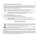
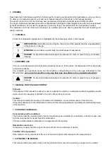
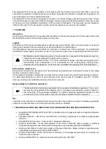
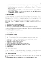
background image

81 


Summary of Contents for CHFPG4

Page 1: ...anuale di istruzioni uso e manutenzione Istruzioni originali FR Manuel d instructions d utilisation et d entretien Traduction de la notice originale EN Instruction use and maintenance manual Translati...

Page 2: ...2...

Page 3: ...3 IT Istruzioni originali Categoria Category II2H3 Tipo di installazione Type of installation FLAME4 A1 B11 B21 FLAME 6 9 B11 B21...

Page 4: ...3 1 Caratteristiche 12 3 2 Dati tecnici 12 3 3 Schemi elettrici 14 4 MOVIMENTAZIONE E TRASPORTO 17 5 PREPARAZIONE DEL LUOGO DI INSTALLAZIONE 17 5 1 PRECAUZIONI PER LA SICUREZZA 17 5 2 LUOGO DI INSTALL...

Page 5: ...EZZA 33 8 2 MANUTENZIONE ORDINARIA RIVOLTA ALL UTILIZZATORE 33 8 2 1 Pulizia del piano refrattario della camera di cottura 33 8 2 2 Pulizia esterna del forno 33 8 3 MANUTENZIONE STRAORDINARIA RIVOLTA...

Page 6: ...ONE D USO I forni a cui fa riferimento il presente manuale sono stati progettati esclusivamente per soddisfare le esigenze di cottura della pizza e di prodotti similari La destinazione d uso sopra rip...

Page 7: ...bi non originali o non specifici per questi modelli m Modifiche e o manomissioni di qualsiasi parte o componente funzionale dell apparecchiatura possono risultare pericolose ed arrecare danni a person...

Page 8: ...ranzia in accordo con le normative comunitarie e decorre dalla data della fattura rilasciata all atto dell acquisto Entro tale periodo saranno sostituiti o riparati gratuitamente solo franco Ns stabil...

Page 9: ...te parti di ricambio originali Non attendere che i componenti siano logorati dall uso prima di procedere alla loro sostituzione Sostituire un componente usurato prima della rottura favorisce la preven...

Page 10: ...PER L INSTALLATORE Verificare che le predisposizioni all accoglimento del forno siano conformi ai regolamenti locali nazionali ed europei L installazione l adattamento ad altro gas e la manutenzione s...

Page 11: ...guanti o appositi utensili per la loro manipolazione Non ostruire mai le aperture di ventilazione e di smaltimento calore Non ostruire i tubi di uscita dei fumi combusti Non depositare all interno o n...

Page 12: ...accensione o assenza di gas deve essere azionato il pulsante di ripristino bruciatore e rimosse le cause che hanno provocato il blocco Il forno deve essere installato perfettamente a livello in un lo...

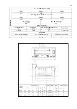
Page 13: ...arghezza Profondit Altezza 105 105 15 Peso kg SCARICO FUMI cm 196 18 DATI ELETTRICI Tensione di alimentazione V Frequenza Hz Potenza massima assorbita W Cavo elettrico 220 230 50 60 50 3 x 0 75 mm2 Al...

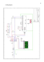
Page 14: ...14 3 3 Schemi elettrici...

Page 15: ...15...

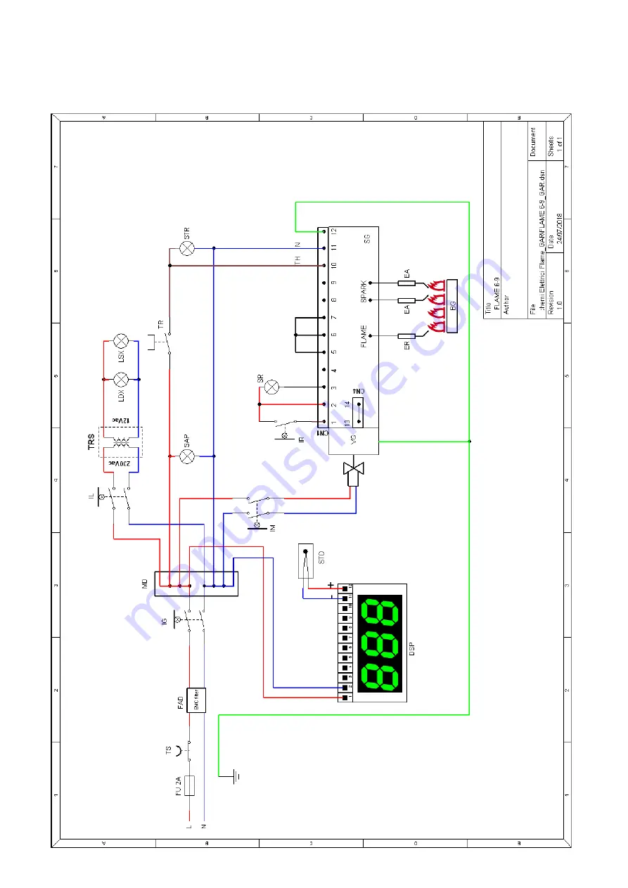
Page 16: ...stato di regolazione Temperature regulation thermostat STR Spia temperatura Temperature reached indicator light IM Interruttore Stand by Stand by switch IR Pulsante di riarmo Gas reset button SR Spia...

Page 17: ...ro di almeno 50 cm nella parete posteriore m Fare attenzione che i bambini non giochino con i componenti dell imballo es pellicole e polistirolo Pericolo di soffocamento 5 PREPARAZIONE DEL LUOGO DI IN...

Page 18: ...forno abbia un adeguata capacit portante che sia in piano e di materiale non combustibile acciaio marmo ecc Verificare che l eventuale vano sottostante non ospiti materiali infiammabili quali liquidi...

Page 19: ...i devono essere facilmente ispezionabili la lunghezza non deve essere superiore ad 1 5 metri e non devono presentare strozzature od essere sottoposti a sforzi di trazione e torsione Porre inoltre part...

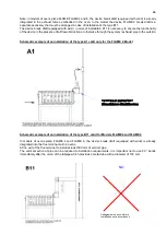
Page 20: ...i aerazione forzata e da condizioni che sono comunque disciplinate dalle leggi nazionale in materia d installazione di apparecchi a gas Nota nei modelli di forni pizza FLAME 4 e FLAME 6 il dispositivo...

Page 21: ...azione l importante non usare curve a 90 subito dopo il bocchettone del terminale di scarico il quale prevede un tubo metallico con diametro 150 mm Schema esemplificativo di un installazione del tipo...

Page 22: ...eratura fumi al camino C Temperature of the smoke at the chimney C 127 135 132 132 134 Massa fumi g s Mass of the smoke g s 41 00 39 52 41 42 42 72 37 61 Valori per singolo forno raccolti con tubo ver...

Page 23: ...1 5 Temperatura fumi al camino C Temperature of the smoke at the chimney C 141 133 131 130 158 Massa fumi g s Mass of the smoke g s 52 45 50 78 56 68 56 23 52 49 Valori per singolo forno raccolti con...

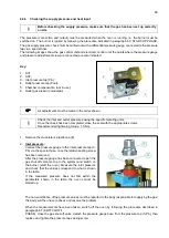
Page 24: ...e di allacciamento e di uscita deve essere fatta con il forno in funzione ovvero il bruciatore deve essere acceso L accensione del bruciatore avviene mediante la procedura indicata nel paragrafo 6 3 F...

Page 25: ...serrare la vite di tenuta delle presa di pressione 3 Pressione in uscita Collegare il manometro mediante l apposito tubo flessibile alla presa di pressione in uscita 4 Pout dopo aver tolto la relativ...

Page 26: ...14 4 0 1 685 m3 h A G30 G31 28 30 37 14 8 28 9 1 104 1 088 kg h B G30 G31 50 14 8 28 9 1 104 1 088 kg h A G30 G31 37 14 8 28 9 1 104 1 088 kg h A Tabella dati tecnici 1 Dati nominali FLAME 6 Tipo di...

Page 27: ...7 5 27 5 10 2 29 2 25 kg h A G30 G31 37 29 17 5 27 5 10 2 29 2 25 kg h A A Regolato nel funzionamento al MAX e al MIN Adjusted at MAX and MIN operating B Regolato nel funzionamento al MIN e fuori serv...

Page 28: ...e regolazioni FLAME 4 Tipo di gas Gas type Pressione in entrata Inlet pressure mbar Diametro iniettore Injector diameter 1 100 mm Regolazione boccola aria primaria H Primary air bush setting H mm G20...

Page 29: ...occola dell aria B come indicato nella seguente figura Al termine della regolazione bloccare nuovamente la vite V Tabella dati tecnici 3 Paesi con relative categorie e pressioni in entrata Paesi Count...

Page 30: ...regolate boccola dell aria e tappo del regolatore di pressione Verificare l assenza di perdite gas Verificare il buon funzionamento dell apparecchio come la regolare interaccensione dei rami del bruci...

Page 31: ...RETTA ACCENSIONE DEL FORNO LASCIARE LA PORTA APERTA FINO A QUANDO IL TERMOMETRO INDICA LA TEMPERATURA DI 200 C Dopo aver collegato il forno alla rete elettrica portare l interruttore generale A in pos...

Page 32: ...rr in stand by fino a quando l interruttore B non verr riportato in posizione 1 prima di riprendere la cottura Per una risultato ottimale necessario che la superficie di cottura refrattario rimanga li...

Page 33: ...di usare getti d acqua utensili vari mezzi ruvidi o abrasivi quali pagliette di acciaio spugne o altro che possano danneggiare le superfici ed in particolare compromettere la sicurezza sotto il profi...

Page 34: ...obabile guasto del termostato di regolazione Verificare il funzionamento del termostato e del termometro Sostituire il componente guasto La lampada di illuminazione interna non si accende Mancanza ali...

Page 35: ...e sul proprietario INFORMAZIONI AGLI UTENTI Ai sensi dell art 13 del Decreto Legislativo 25 luglio 2005 n 151 Attuazione delle Direttive 2002 95 CE 2002 96 CE 2003 108 CE relative alla riduzione dell...

Page 36: ...36 FR Traduction de la notice originale Cat gorie Category II2H3 Type d installation Type of installation FLAME4 A1 B11 B21 FLAME 6 9 B11 B21...

Page 37: ...D ENTRETIEN 44 3 SP CIFICATIONS G N RALES 45 3 1 Caract ristiques 45 3 2 Donn es techniques 45 3 3 Sch mas de c blage 47 4 MANUTENTION ET TRANSPORT 50 5 PR PARATION DI LIEU D INSTALLATION 50 5 1 PR C...

Page 38: ...RIT 66 8 2 ENTRETIEN ORDINAIRE SOUS LA RESPONSABILIT DE L UTILISATEUR 66 8 2 1 Nettoyage de la sole r fractaire de la chambre de cuisson 66 8 2 2 Nettoyage externe du four 66 8 3 ENTRETIEN EXTRAORDINA...

Page 39: ...1 2 DESTINATION D USAGE Les fours qui font l objet de ce manuel ont t exclusivement con us pour la cuisson de pizzas et de produits similaires La destination d emploi report e ci dessus et les configu...

Page 40: ...appareil peuvent s av rer dangereuses et tre la cause de dommage pour les biens et les personnes Il est strictement interdit pour les raisons susmentionn es de manipuler les pi ces scell es par la fa...

Page 41: ...uniquement franco notre usine les pi ces d tach es qui pour des raisons d ment constat es et sans quivoques pr sentent des d fauts de fabrication l exception des composants lectriques et de ceux soumi...

Page 42: ...tre d assistance agr le plus proche 1 12 PI CES D TACH ES Utiliser exclusivement des pi ces de rechange originales Ne pas attendre que les composants soient trop us s avant de les remplacer Remplacer...

Page 43: ...TIONS POUR L INSTALLATEUR V rifier que l emplacement pr vu pour le four soit conforme la r glementation locale nationale et europ enne L installation l adaptation un autre gaz et l entretien extraordi...

Page 44: ...ser des gants ou des ustensiles adapt s pour les manipuler Ne jamais obstruer les ouvertures de ventilation et d vacuation de la chaleur Ne pas obstruer les tuyaux d vacuation de fum e de combustion N...

Page 45: ...faut actionner le bouton de reprise du br leur et supprimer les causes qui ont provoqu le blocage Le four doit tre install parfaitement niveau dans un local bien a r et de dimensions ad quates 3 2 Don...

Page 46: ...Largeur Profondeur Hauteur 105 105 15 Poids kg VACUATION FUM ES cm 196 18 DONN ES LECTRIQUES Tension d alimentation V Fr quence Hz Puissance maximum absorb e W C ble lectrique 220 230 50 60 50 3 x 0 7...

Page 47: ...47 3 3 Sch mas de c blage...

Page 48: ...48...

Page 49: ...2 A TR Thermostat de r glage Control thermostat STR Voyant temp rature Temperature indicator light IM Interrupteur Stand by Standby switch IR Bouton de r armement Reset button SR Voyant de non mise en...

Page 50: ...ace libre de 50 cm minimum vers la paroi post rieure m Ne pas laisser les enfants jouer avec l emballage ex films transparents et polystyr ne Danger d touffement 5 PR PARATION DI LIEU D INSTALLATION 5...

Page 51: ...appui du four ait une capacit portante adapt e et qu il soit plat et en mat riau non combustible acier marbre etc V rifier que l ventuel compartiment en dessous du four ne contienne pas de mat riaux i...

Page 52: ...rescriptions des normes en vigueur En cas d utilisation de tuyaux d acier flexibles ceux ci doivent tre facilement contr lables Leur longueur ne doit pas d passer 1 5 m tre et ils ne doivent pas pr se...

Page 53: ...ence de syst mes de ventilation forc e et les conditions qui sont n anmoins r gies par les lois nationales dans le domaine de l installation des appareils gaz Remarque dans les mod les de fours pizza...

Page 54: ...l est important de ne pas utiliser des coudes 90 imm diatement apr s l union du tuyau d chappement qui fournit un tube m tallique d un diam tre de 150 mm Exemple sch matique d une installation de la B...

Page 55: ...fum es la chemin e C Chimney smoke temperature C 127 135 132 132 134 Masse fum es g s Smoke mass g s 41 00 39 52 41 42 42 72 37 61 Valeurs pour chaque four recueillies avec un conduit vertical de 1 m...

Page 56: ...ure fum es la chemin e C Chimney smoke temperature C 141 133 131 130 158 Masse fum es g s Mass of the smoke g s 52 45 50 78 56 68 56 23 52 49 Valeur pour chaque four recueillies avec un conduit vertic...

Page 57: ...chement et de sortie doit tre faite avec le four en fonction donc avec le br leur allum L allumage du br leur se fait en suivant la m thode indiqu e dans le paragraphe 6 3 PHASE DE D MARRAGE La v rifi...

Page 58: ...er et serrer la vis d tanch it des mesures de pression 8 Pression en sortie Avec le tuyau flexible appropri connecter le manom tre la prise de pression en sortie 4 Pout apr s avoir enlev la vis d tanc...

Page 59: ...25 14 8 14 4 0 1 685 m3 h A G30 G31 28 30 37 14 8 28 9 1 104 1 088 kg h B G30 G31 50 14 8 28 9 1 104 1 088 kg h A G30 G31 37 14 8 28 9 1 104 1 088 kg h A Tableau des donn es techniques 1 Donn es nomin...

Page 60: ...B G30 G31 50 29 17 5 27 5 10 2 29 2 25 kg h A G30 G31 37 29 17 5 27 5 10 2 29 2 25 kg h A A R gl dans le fonctionnement au MAX et au MIN Adjusted to MAX and MIN operating mode A R gl dans le fonctionn...

Page 61: ...urs et r glages FLAME 4 Type de gaz Gas type Pression en entr e Inlet pressure mbar Diam tre injecteur Injector diameter 1 100 mm R glage douille air primaire H Primary air bush adjustment H mm G20 20...

Page 62: ...u dans la figure suivante la fin du r glage bloquer nouveau la vis V Tableau donn es techniques 3 Pays avec les cat gories et pressions en entr e appropri es Pays Countries Cat gorie Category Sommaire...

Page 63: ...r gulateur de pression V rifier l absence de fuite de gaz V rifier le bon fonctionnement de l appareil comme l inter allumage des branches du br leur la stabilit et l aspect des flammes La combustion...

Page 64: ...DE D MARRAGE POUR UNE CORRECT ALLUMAGE LAISSER LE PORTE OUVERTE JUSQU A LA TEMP RATURE ARRIVE A 200 C Apr s avoir branch le four au r seau lectrique amener l interrupteur g n ral A la positon 1 L affi...

Page 65: ...1 avant de reprendre la cuisson Pour un r sultat optimal il faut que la surface de cuisson r fractaire reste libre d environ 20 Cette consigne permet une limination optimale des vapeurs aqueuses caus...

Page 66: ...compromettre la s curit du point de vue de l hygi ne 8 2 1 Nettoyage de la sole r fractaire de la chambre de cuisson Le nettoyage doit tre effectu la fin de chaque utilisation selon les normes hygi ni...

Page 67: ...t en panne La lampe d clairage interne ne s allume pas Manque d alimentation lectrique sur la lampe V rifier le raccordement lectrique Interrupteur lampe en panne Remplacer l interrupteur lampe Transf...

Page 68: ...les animaux La responsabilit pour tout dommage des personnes et animaux retombe sur le propri taire INFORMATIONS AUX UTILISATEURS conform ment l art 13 D cret L gislatif 25 juillet 2005 no 2005 Ex cu...

Page 69: ...69 EN Translation of the original instructions Categoria Category II2H3 Tipo di installazione Type of installation FLAME 4 A1 B11 B21 Flame 6 9 B11 B21...

Page 70: ...IAN 77 3 GENERAL SPECIFICATIONS 78 3 1 Features 78 3 2 Technical data 78 3 3 Wiring diagrams 80 4 HANDLING AND TRANSPORT 83 5 PREPARING THE INSTALLATION SITE 83 5 1 SAFETY PRECAUTIONS 83 5 2 OVEN INST...

Page 71: ...INE MAINTENANCE TO BE PERFORMED BY THE USER 98 8 2 1 Cleaning the refractory surface of the cooking chamber 99 8 2 2 Externally cleaning the oven 99 8 3 UNPLANNED MAINTENANCE TO BE PERFORMED BY TECHNI...

Page 72: ...ilar products The intended use described above and the machine configurations are the only uses authorized by the Manufacturer do not use the machine in any way that does not adhere to the provided in...

Page 73: ...raordinary maintenance Extraordinary maintenance operations must be performed by qualified personnel trained to work on the rolling machine referred to in this manual It is advisable to stipulate a ma...

Page 74: ...ays carry out constant and accurate maintenance Authorize only personnel with adequate skills behaviour and proper training to use the product The warranty shall also be invalidated in the case of ful...

Page 75: ...s all relevant data including Manufacturer data the serial number and the CE conformity to type marking The CE marking is issued by a notified body following certification tests and the surveillance a...

Page 76: ...lts Install and operate the equipment only in an adequately ventilated in accordance with the rules in force Verify that the volume of the room is appropriate and that the ventilation systems natural...

Page 77: ...t pipes Do not place flammable materials inside or near the oven Do not use the oven chamber to store materials of any kind Do not use abrasive products corrosive substances metal scrapers or any othe...

Page 78: ...If there is an ignition failure or absence of gas the burner reset button must be activated and the causes that led to the block must be rectified The oven must be installed perfectly level in a good...

Page 79: ...er dimensions cm Width Depth Height 105 105 15 Weight kg FLUE GAS cm 196 18 ELECTRIC DATA Supply voltage V Frequency Hz Maximum power absorbed W Power cable 220 230 50 60 50 3 x 0 75 mm2 Other data Ga...

Page 80: ...80 3 3 Wiring diagrams...

Page 81: ...81...

Page 82: ...tato di regolazione Control thermostat STR Spia temperatura Temperature indicator light IM Interruttore Stand by Standby switch IR Pulsante di riarmo Reset button SR Spia mancata accensione Flame fail...

Page 83: ...e and or repairs Leave a gap of at least 50 cm from the back wall m Make sure that children do not play with the packaging components e g film and polystyrene Suffocation hazard 5 PREPARING THE INSTAL...

Page 84: ...NG THE OVEN Make sure that the oven s support surface has an adequate load bearing capacity is level and is made of non combustible materials steel marble etc Check that the underlying compartment doe...

Page 85: ...performing the installation operations a check must be performed to ensure that there are no gas leaks This check can be performed using a leak detector spray or non corrosive foaming substances It i...

Page 86: ...of airflow obstruction or otherwise through the system exhaust pipe to the outside Schematic example of an installation of the type A1 valid only for the FLAME 4 Model Schematic example of an install...

Page 87: ...eter 180 mm The vertical section of pipe can be reduced to installation requirements it is important not to use 90 bends right after the break draft device Schematic example of an installation of the...

Page 88: ...2 4 2 4 2 5 2 4 2 2 Temperatura fumi al camino C Chimney smoke temperature C 125 0 128 0 120 0 124 0 126 0 Massa fumi g s Smoke mass g s 40 99 38 80 40 98 42 02 36 56 Valori per singolo forno raccolti...

Page 89: ...the superimposition of the two ovens means that the lower oven is equipped with an inclined vertical tube at 45 in order to be able to discharge the smoke away from the discharge outlet of the upper...

Page 90: ...fic metering units Once the check has been completed close the seal with the appropriate screws Recommended tightening torque 1 0 Nm 1 Remove the modulator s plastic cap E 2 Inlet pressure Connect the...

Page 91: ...n control panel switch B positioned on MIN Whilst keeping the nut C locked tighten the screw D to increase the pressure and loosen it to decrease the pressure 6x1 slotted screwdriver Reposition the mo...

Page 92: ...cal data table 1 FLAME 9 nominal data Tipo di gas Gas type Pressione nominale ingresso Nominal inlet pressure mbar Portata termica nominale Nominal heat input kW Portata termica ridotta Reduced heat i...

Page 93: ...t this operation the oven s lower front panel must be removed as indicated below 1 Remove the screws that secure the front panel the parts circled in the figure 2 Remove the front panel to access the...

Page 94: ...n entrata Inlet pressure mbar Diametro iniettore Injector diameter 1 100 mm Regolazione boccola aria primaria H Primary air bush adjustment H mm G20 20 400 14 G20 25 400 14 G25 20 400 14 G25 25 400 14...

Page 95: ...SK TR II2H3 2H 3 G20 G30 G31 20 28 30 37 17 20 25 25 35 45 DE II2ELL3B P 2E 2LL 3B P G20 G25 G30 G31 20 20 50 17 18 42 5 25 25 57 5 NL II2EK3B P 2E 2K 3B P G20 G25 3 G30 G31 20 25 28 30 17 20 25 25 3...

Page 96: ...UPPLY INDICATOR LIGHT G ALARM SWITCH OFF INDICATOR LIGHT AND RESET BUTTON H CHAMBER LIGHT SWITCH Control panel with a digital thermometer A MAIN SWITCH B OVEN STANDBY SWITCH C DIGITAL THERMOMETER D ME...

Page 97: ...ularly regarding pizza and similar products time and temperatures depend on the shape and thickness of the dough as well as the quantity and type of the additional ingredients For these reasons it is...

Page 98: ...h would cause the chamber temperature to drop Keep oil and fats from dripping onto the bottom as they could burn at high temperatures 7 7 SWITCH OFF PHASE To shut down the oven turn the thermostat kno...

Page 99: ...cloth 8 2 2 Externally cleaning the oven The cleaning of the external oven surface the external parts in stainless steel the inspection window and the control panel must be done with the oven cold and...

Page 100: ...switch is faulty Replace the lamp switch The transformer is faulty Replace the transformer The lamp has burnt out Replace the lamp The cooking chamber does not heat up properly The set temperatures ar...

Page 101: ...ccording to Art 13 of the Leg Decree No 151 of 25 July 2005 Implementation of Directives 2002 95 CE 2002 96 CE 2003 108 CE regarding the restriction of the use of certain hazardous substances in elect...

Page 102: ...102 RU Category II2H3 Type of installation FLAME4 A1 B11 B21 FLAME 6 9 B11 B21...

Page 103: ...8 107 1 9 107 1 10 107 1 11 108 1 12 108 1 13 108 1 14 109 2 109 2 1 109 2 2 110 2 3 110 3 111 3 1 111 3 2 111 3 3 113 4 116 5 116 5 1 116 5 2 117 6 117 6 1 117 6 2 117 6 2 1 117 6 2 1 1 118 6 2 3 11...

Page 104: ...104 7 6 131 7 7 132 8 132 8 1 132 8 2 132 8 2 1 132 8 2 2 132 8 3 132 9 133 10 134...

Page 105: ...105 1 1 1 m 1 2 m 1 3 1 4...

Page 106: ...106 1 5 II2H3 1 6 m B11 B21 1 7 2016 426 9 2016 2009 142 EC EN 203 1 EN 203 2 2 EN 203 3 EN 437...

Page 107: ...107 2014 35 2006 95 2014 30 2004 108 89 391 2006 42 95 16 85 374 1999 34 EC 2002 95 2002 96 EC 2003 108 EC 1935 2004 80 590 89 109 1 8 1999 44 1 9 1 10...

Page 108: ...108 1 11 1 12 1 13 CE CE...

Page 109: ...109 RU 1 14 2 2 1...

Page 110: ...110 2 2 2 3...

Page 111: ...111 3 3 1 3 2 FLAME 4 113 91 47 70 70 15 132 15 220 230 50 60 50 3 x 0 75 2 A1 B11 B21 I FLAME 6 113 126 47 70 105 15 164 15 220 230 50 60 50 3 x 0 75 2 B11 B21 I...

Page 112: ...112 FLAME 9 148 126 47 105 105 15 196 18 220 230 50 60 50 3 x 0 75 2 B11 B21 I...

Page 113: ...113 3 3...

Page 114: ...114...

Page 115: ...SAP Power supply indicator light FU 2 Fuse 2 A TR Control thermostat STR Temperature indicator light IM Standby switch IR Reset button SR Flame failure indicator light VG Solenoid valve SG Electronic...

Page 116: ...116 4 25 50 50 m 5 5 1...

Page 117: ...117 5 2 25 50 50 6 6 1 4 2 F 6 2 6 2 1 3...

Page 118: ...118 6 2 1 1 6 2 2 1 13 1 5 6 2 3 A1 B11...

Page 119: ...119 B21 FLAME 4 FLAME 6 FLAME 9 B11 B11 A1 FLAME 4...

Page 120: ...120 Collegamento non conforme Installation not in accordance NO B11 FLAME 4 FLAME 6 FLAME 4 FLAME 6 500 90 150 B11 FLAME 9 FLAME 9 180 500 180 90...

Page 121: ...mass g s 41 00 39 52 41 42 42 72 37 61 1 150 Values for a single oven collected with a 1 metre vertical tube with a diameter of 150 mm Flame 6 G30 G20 G25 G25 1 G25 3 Chimney smoke pressure Pa 2 4 2 4...

Page 122: ...Chimney smoke pressure Pa 1 9 1 8 1 8 1 9 1 5 C Chimney smoke temperature C 141 133 131 130 158 Smoke mass g s 52 45 50 78 56 68 56 23 52 49 1 180 Values for a single oven collected with a 1 metre ver...

Page 123: ...123 FLAME 4 FLAME 6 45 6 2 4 6 3 1 EV1 2 EV2 3 Pin 4 Pout 5 6...

Page 124: ...124 1 0 1 E 2 3 Pin 6 7 3 Pin 3 4 Pout 4 B MAX 10 5 B MIN C D 6x1 E...

Page 125: ...37 14 8 28 9 1 104 1 088 B G30 G31 50 14 8 28 9 1 104 1 088 A G30 G31 37 14 8 28 9 1 104 1 088 A 1 FLAME 6 Gas type Nominal inlet pressure Nominal heat input Reduced heat input Valve outlet pressure a...

Page 126: ...9 17 5 10 3 6 3 07 3 A G20 25 29 17 5 10 3 6 3 07 3 A G25 20 29 17 5 15 5 5 3 57 3 A G25 25 29 17 5 15 5 5 3 57 3 A G25 1 25 29 17 5 17 6 2 3 56 3 A G25 3 25 29 17 5 13 4 5 3 489 m3 h A G30 G31 28 30...

Page 127: ...G25 25 335 14 G25 1 25 335 14 G25 3 25 335 14 G30 G31 28 30 37 195 18 G30 G31 50 195 18 G30 G31 37 195 18 2 FLAME 6 Gas type Inlet pressure Injector diameter 1 100 H Primary air bush adjustment H G20...

Page 128: ...e Nominal inlet pressure Minimum inlet pressure Maximum inlet pressure AT CH II2H3B P 2H 3B P G20 G30 G31 20 50 17 42 5 25 57 5 AL BA BG DK EE FI HR LT LV MK NO RO SE SI UA II2H3B P 2H 3B P G20 G30 G3...

Page 129: ...7 25 25 45 IS CY MT I3B P 3B P G30 G31 28 30 25 35 LU BE FR I3 3 G30 G31 28 30 37 20 25 35 45 LU I2E 2E G20 20 17 25 BE I2E R 2E R G20 G25 20 25 17 20 25 30 FR I2Esi 2Esi G20 G25 20 25 17 20 25 30 7 7...

Page 130: ...130 A B C D E F G H 7 2 200 C 1 8 300 350 C 7 3 200 C A 1 D B 0 B 1 7 4...

Page 131: ...131 7 5 380 C 3 3 5 1 30 40 380 2 3 4 5 B 0 B 1 20 7 6 H 1...

Page 132: ...132 7 7 D 0 A 0 8 8 1 89 391 8 2 8 2 1 350 60 100 C 8 2 2 8 3...

Page 133: ...133 9 0 1 1 PF Schuko...

Page 134: ...134 10 13 151 25 2005 2002 95 2002 96 2003 108...

Page 135: ...135 ES Traducci n de las instrucciones originales Categor a Category II2H3 Tipo di instalaci n Type of installation FLAME4 A1 B11 B21 FLAME 6 9 B11 B21...

Page 136: ...OS GEN RICOS 144 3 1 Caracter sticas 144 3 2 Datos T cnicos 144 3 3 Esquemas el ctricos 146 4 MANIPULACI N Y TRANSPORTE 149 5 PREPARACI N DEL LUGAR DE INSTALACI N 149 5 1 PRECAUCIONES DE SEGURIDAD 149...

Page 137: ...IMIENTO ORDINARIO PARA USUARIOS 165 8 2 1 Limpieza del plano refractario de la c mara de cocci n 165 8 2 2 Limpieza externa del horno 165 8 3 MANTENIMIENTO EXTRAORDINARIO PARA T CNICOS 165 9 ALARMAS Y...

Page 138: ...hornos a los que se refiere este manual han sido dise ados y fabricados solamente para la cocci n de pizza y productos similares El uso previsto mencionado y las configuraciones previstas para estos a...

Page 139: ...nmediato Mantenimiento extraordinario Las operaciones de mantenimiento extraordinario deben ser efectuadas por personal cualificado y habilitado para intervenir en el aparato al que se refiere este ma...

Page 140: ...el producto solo a personas con capacidad y aptitud probadas y con formaci n espec fica para ello La garant a tambi n queda anulada en caso de incumplimiento total o parcial de las instrucciones conte...

Page 141: ...l marcado CE de conformidad al tipo El marcado CE es expido por un Organismo Notificado tras la realizaci n de ensayos de certificaci n y de la actividad de supervisi n del producto que establece la n...

Page 142: ...gas cumpla todos los requisitos para la correcta conexi n del aparato seg n las normas vigentes No efect e conexiones el ctricas temporales con cables provisionales o no aislados Compruebe que la pue...

Page 143: ...cos u otras sustancias o herramientas que pudieran arruinar la superficie Se debe limpiar cuando el horno est fr o No apoyar objetos o sentarse sobre la puerta No dejar el aparato sin supervisi n En c...

Page 144: ...o En caso de que no se encienda el aparato o no haya gas se debe accionar el bot n de restauraci n del quemador y se deber a haber retiradola causa que provoc el bloqueo El horo debe instalarse perfec...

Page 145: ...de cocci n cm Longitud Profundidad Altura 105 105 15 Peso kg ESCAPE DE GASES cm 196 18 INFORMACI N EL CTRICA Tensi n de alimentaci n V Frecuencia Hz Potencia m xima absorbida W Cable el ctrico 220 230...

Page 146: ...146 3 3 Esquemas el ctricos...

Page 147: ...147...

Page 148: ...A TR Termostato de regulaci n Control thermostat STR Luz temperatura Temperature indicator light IM Interruptor Stand by Standby switch IR Bot n de rearme Reset button SR Luz no encendido Flame failu...

Page 149: ...araci n Dejar un espacio libre de al menos 50 cm en relaci n con la pared posterior m Procure que no haya ni os jugando con los componentes de embalaje por ejemplo pl sticos y poliestireno Peligro de...

Page 150: ...de apoyo tenga la capacidad de carga adecuada que est en terreno llano y que sea de material no combustible acero marmol etc Comprobar que el alojamiento inferior no contenga materiales infamables com...

Page 151: ...exibles deben ser f cilmente registrables su longitud no debe superar 1 5 metro y no deben presentar estrangulamientos ni estar sometidos a esfuerzos de tracci n y torsi n Ponga especial cuidado en qu...

Page 152: ...las leyes nacionales en materia de instalaci n de aparatos de gas Nota en los modelos de hornos de pizza FLAME 4 y 6 el proyecto de ruptura del dispositivo a prueba de viento de la chimenea ya est int...

Page 153: ...importante no utilizar codos de 90 inmediatamente despu s de la uni n del tubo de escape que proporciona un tubo de metal con un di metro de 150 mm Ejemplo esquem tico de una instalaci n del tipo B11...

Page 154: ...2 Temperatura humo de la chimenea C Chimney smoke temperature C 127 135 132 132 134 Fuerza humo g s Smoke mass g s 41 00 39 52 41 42 42 72 37 61 Valores para un nico horno recogidos con un tubo verti...

Page 155: ...mperatura humo de la chimenea C Chimney smoke temperature C 141 133 131 130 158 Fuerza humo g s Smoke mass g s 52 45 50 78 56 68 56 23 52 49 Valores para un nico horno recogidos con un tubo vertical d...

Page 156: ...y de salida deve hacerse con el horno en funcionamiento es decir el quemador debe estar encendido El encendido del quemador ocurre mediante el procedimiento indicado en el p rrafo 6 3 FASE DE INICIO...

Page 157: ...rrar las roscas de tensi n de la toma de presi n 3 Presi n de salida Conectar el man metro mediante el toblo flexible correcto a la toma de presi n de salida 4 Pout despu s de retirar la rosca de tens...

Page 158: ...25 14 8 14 4 0 1 685 m3 h A G30 G31 28 30 37 14 8 28 9 1 104 1 088 kg h B G30 G31 50 14 8 28 9 1 104 1 088 kg h A G30 G31 37 14 8 28 9 1 104 1 088 kg h A Tabla de datos t cnicos 1 Datos nominales FLA...

Page 159: ...5 27 5 10 2 29 2 25 kg h A G30 G31 37 29 17 5 27 5 10 2 29 2 25 kg h A A Regulado en el funcionamiento al MAX y al MIN Adjusted to MAX and MIN operating mode B Regulado en el funcionamiento al MIN y...

Page 160: ...po de gas Gas type Presi n de entrada Inlet pressure mbar Di metro del inyector Injector diameter 1 100 mm Regulaci n de la caja de ventilaci n primaria H Primary air bush adjustment H mm G20 20 335 1...

Page 161: ...se indica en la siguiente figura Cuando se termine de realizar la regulaci n bloquee nuevamente la rosca V Tabla de datos t cnicos 3 Pa ses con categor as y presi n de entrada espec fica Pa ses Count...

Page 162: ...de ventilaci n y tap n del regulador de presi n Comprobar la ausencia de fugas de gas Verificar el buen funcionamiento del aparato como la regulaci n de los sectores del quemador la estabilidad y el...

Page 163: ...a vez 7 3 FASE DE INICIO ATENCI N PARA UNA CORRECTA ACCENSION DEL HORNO DEJAR LA PUERTA ABIERTA HASTA EL TEMOMETRO INDICA LA TEMPERATURA DE 200 C Despu s de conectar el horno a la red el ctrica ponga...

Page 164: ...ue se ponga el interruptor B en la posici n 1 antes de reanudar la cocci n Para un resultado ideal es necesario que el 20 de la superficie de cocci n plano refractario permanezca libre Esto permite el...

Page 165: ...del plano refractario de la c mara de cocci n La limpieza se debe realizar al final de cada uso y siempre siguiendo las normas higi nicas y respentando las funciones de la m quina Antes de comenzar h...

Page 166: ...na no se enciende Falta la alimentaci n el ctrica en la iluminaci n Comprobar la conexi n el ctrica Comprobar la bombilla averiada Sustituir el interruptor de la iluminaci n Transformador defectuoso S...

Page 167: ...l propietario INFORMACI N PARA EL USUARIO conforme al art 13 del Decreto Legislativo italiano n 151 del 25 de julio de 2005 Aplicaci n de las Directivas 2002 95 CE 2002 96 CE 2003 108 CE relativas a l...

Page 168: ...168 DE bersetzung der Originalanleitung Kategorie Category II2H3 Installationstypologie Type of installation FLAME4 A1 B11 B21 FLAME 6 9 B11 B21...

Page 169: ...NWEISE F R DEN WARTUNGSTECHNIKER 176 3 ALLGEMEINE MERKMALE 177 3 1 Eigenschaften 177 3 2 Technische Daten 177 3 3 Schaltpl ne 179 4 HANDHABUNG UND TRANSPORT 182 5 VORBEREITUNG DES AUFSTELLUNGSORTS 182...

Page 170: ...98 8 2 ORDENTLICHE INSTANDHALTUNG DURCH DEN BENUTZER 198 8 2 1 Reinigung des Schamottstein Bodens in der Backkammer 198 8 2 2 Au enreinigung des Ofens 198 8 3 AUSSERORDENTLICHE INSTANDHALTUNG DURCH FA...

Page 171: ...Handbuch behandelten fen wurden ausschlie lich zum Backen von Pizza und hnlichen Produkten entwickelt Der oben genannte Bestimmungszweck und die vorgesehenen Konfiguration f r diese Ger te sind die ei...

Page 172: ...n verursachen Aus den genannten Gr nden ist es strikt verboten nderungen an den vom Hersteller versiegelten Teilen vorzunehmen Der Hersteller ist nicht haftbar f r Auswirkungen die aufgrund einer unsa...

Page 173: ...t Um die gesetzliche Garantie auf die sich die Richtlinie 1999 44 EG bezieht voll beanspruchen zu k nnen muss der Benutzer die Vorschriften dieses Handbuches genau einhalten und insbesondere Stets inn...

Page 174: ...rschlissene Komponenten rechtzeitig auswechseln damit Unf lle wegen pl tzlichem Defekt vermieden werden welche zu schweren Verletzungen und Sachsch den f hren k nnen Die regelm igen Wartungskontrollen...

Page 175: ...rung gem den geltenden Vorschriften 2 SICHERHEITSHINWEISE 2 1 HINWEISE F R DEN INSTALLATEUR berpr fen dass die Voreinsetzungen f r den Ofeneinbau den lokalen nationalen und europ ischen Regelungen ent...

Page 176: ...diese Verbrennungen verursachen k nnen Kinder au er Reichweite halten Benutzt man Bleche oder flache T pfe sind stets Ofenhandschuhe oder daf r geeignete Utensilien zu verwenden L ftungs und W rmeable...

Page 177: ...selektrode zeigt an ob die Flamme vorhanden ist Wenn es keine Z ndung oder kein Gas gibt m ssen der Brenner R ckstellknopf gedr ckt und die Ursachen der Sperre beseitigt werden Der Ofen muss in einem...

Page 178: ...en der Backkammer cm Breite Tiefe H he 105 105 15 Gewicht kg RAUCHABZUG cm 196 18 ELEKTRISCHE ANGABEN Versorgungsspannung V Frequenz Hz Maximale Leistungsaufnahme W Stromkabel 220 230 50 60 50 3 x 0 7...

Page 179: ...179 3 3 Schaltpl ne...

Page 180: ...180...

Page 181: ...2A Fuse 2 A TR Regelthermostat Control thermostat STR Kontrollleuchte Temperatur Temperature indicator light IM Standby Schalter Standby switch IR R ckstelltaste Reset button SR Kontrollleuchte keine...

Page 182: ...e zu haben An der r ckseitigen Wand einen Abstand von mindestens 50 cm vorsehen m Darauf achten dass Kinder nicht mit den Verpackungsteilen z B Folie und Polystyrol spielen Erstickungsgefahr 5 VORBERE...

Page 183: ...rt werden 6 1 AUFSTELLUNG DES OFENS Sicherstellen dass die Abstellplatte des Ofens eine ausreichende Tragf higkeit aufweist eben und nicht brennbar Stahl Marmor usw ist Sich vergewissern dass im darun...

Page 184: ...n sein die L nge darf nicht mehr als 1 5 Meter betragen und es d rfen keine Verengungen vorliegen und die Leitungen d rfen keinen Zug oder Torsionskr ften ausgesetzt sein Es ist ebenfalls besonders zu...

Page 185: ...und Bedingungen die durch die nationalen Gesetze im Bereich der Installation von Gasger ten geregelt sind ab Anmerkung Bei den Pizzaofenmodellen FLAME 4 und FLAME 6 ist die Str mungssicherung bereits...

Page 186: ...direkt hinter der ffnung des Ausgangs des Rauchabzugs welcher ein Metallrohr mit einem Durchmesser von 150 mm vorsieht keine 90 Kurve zu verwenden Schematisches Beispiel einer Installation des Typs B1...

Page 187: ...a 2 0 1 8 2 1 2 1 2 2 Rauchtemperatur im Schornstein C Chimney smoke temperature C 127 135 132 132 134 Rauchmasse g s Smoke mass g s 41 00 39 52 41 42 42 72 37 61 Werte f r jeden Ofen mit 1 m langem v...

Page 188: ...1 5 Rauchtemperatur im Schornstein C Chimney smoke temperature C 141 133 131 130 158 Rauchmasse g s Smoke mass g s 52 45 50 78 56 68 56 23 52 49 Werte f r jeden Ofen mit 1 m langem vertikalem Rohr Du...

Page 189: ...Die Druckmessung am Eingang und Ausgang muss bei eingeschaltetem Ofen durchgef hrt werden d h der Brenner muss gez ndet haben Der Brenner wird nach dem in Abschnitt 6 3 EINSCHALTPHASE beschriebenen Ve...

Page 190: ...be des Druckanschlusses wieder anbringen und anziehen 3 Ausgangsdruck Den Druckmesser nach dem Entfernen der Dichtschraube ber den entsprechenden Schlauch mit dem Druckanschluss am Ausgang 4 Pout verb...

Page 191: ...14 8 14 4 0 1 685 m3 h A G30 G31 28 30 37 14 8 28 9 1 104 1 088 kg h B G30 G31 50 14 8 28 9 1 104 1 088 kg h A G30 G31 37 14 8 28 9 1 104 1 088 kg h A Tabelle technische Daten 1 Nenndaten FLAME 6 Gas...

Page 192: ...17 5 27 5 10 2 29 2 25 kg h A G30 G31 37 29 17 5 27 5 10 2 29 2 25 kg h A A Betrieb auf MAX und MIN eingestellt Adjusted to MAX and MIN operating mode B Betrieb auf MIN und bei au er Betrieb auf MAX...

Page 193: ...stellungen FLAME 4 Gastypologie Gas type Eingangsdruck Inlet pressure mbar Durchmesser Injektor Injector diameter 1 100 mm Buchse Prim rlufteinstellung H Primary air bush adjustment H mm G20 20 335 18...

Page 194: ...2 und wie in der folgenden Abbildung dargestellt Die Schraube V wieder anziehen sobald die Einstellung abgeschlossen ist Tabelle technische Daten 3 L nder mit entsprechenden Kategorien und Eingangsdr...

Page 195: ...ten Teile Luftbuchse und Druckreglerkappe versiegeln Sicherstellen dass keine Gaslecks vorhanden sind Den einwandfreien Betrieb des Ger ts sicherstellen wie z B die ordnungsgem e Querz ndung der Brenn...

Page 196: ...geschoben wird 7 3 EINSCHALTPHASE F R EINE KORREKTE EINSCHALTUNG DES OFENS DIE T R OFFEN LASSEN BIS DAS THERMOMETER DIE TEMPERATUR 200 C ANZEIGT Nach dem Anschluss des Ofens an das Stromnetz den Haupt...

Page 197: ...bis der Schalter B wieder in die Position 1 gebracht wird bevor wieder mit dem Backen begonnen wird F r optimale Ergebnisse sollten zirka 20 der Backfl che Schamottsteinboden frei bleiben Auf diese We...

Page 198: ...Sicherheit aus hygienischer Sicht beeintr chtigen sind absolut zu meiden 8 2 1 Reinigung des Schamottstein Bodens in der Backkammer Die Reinigung muss am Ende jeder Nutzung unter Beachtung der Hygien...

Page 199: ...s berpr fen Das defekte Teil ersetzen Die Innenlampe schaltet sich nicht ein Lampe ohne Stromversorgung Den Stromanschluss berpr fen Lampenschalter defekt Den Lampenschalter auswechseln Trafo defekt D...

Page 200: ...der Besitzer INFORMATIONEN F R DEN BENUTZER Gem Art 13 Gesetzesdekrets Nr 151 vom 25 Juli 2005 Umsetzung der Richtlinien 2002 95 EG 2002 96 EG 2003 108 EG zur Beschr nkung der Verwendung bestimmter ge...

Page 201: ...201 EXPLODED VIEW DRAWINGS AND SPARE PARTS...

Page 202: ...202...

Page 203: ...203...

Page 204: ...DJUSTMENT BUSH 20 20X1X42 13 S74TB57002 1 2 GAS 4 OVEN GALVANISED PIPE 14 A92UG86003 FLAME 4 NATURAL GAS INJECTOR 335 14 A92UG86004 FLAME 4 LPG GAS INJECTOR 195 22 A92BU86001 GAS 4 OVEN BURNER 23 A92E...

Page 205: ...GAS 6 COPPER PIPE 5 A92VA86002 GAS 6 AIR ADJUSTMENT BUSH 24 22X1X42 13 S74TB57001 1 2 GAS 6 OVEN GALVANISED PIPE 14 A92UG86001 FLAME 6 NATURAL GAS INJECTOR 400 14 A92UG86002 FLAME 6 LPG GAS INJECTOR...

Page 206: ...A92VA86004 GAS 9 AIR ADJUSTMENT BUSH 26 24X1X42 13 S74TB57001 1 2 GAS 6 9 OVEN GALVANISED PIPE 14 A92UG86005 FLAME 9 NATURAL GAS INJECTOR 500 14 A92UG86008 FLAME 9 LPG GAS INJECTOR 285 22 A92BU86003...

Page 207: ...Qty 1 A00PT57001 CERAMIC GLASS 515X94X4 mm 1 2 S66CG64011 4 6 INNER DOOR ASSEMBLY 1 3 A94NC00006 ADHESIVE JOINT 6x2 mm 2 4 S66PT64001 4 6 DOOR ASSEMBLY 1 5 S42MG64006 LEFT SUPPORT HANDLE 1 6 S42MG6400...

Page 208: ...Qty 1 A00PT64001 CERAMIC GLASS 865X94X4 mm 1 2 A94NC00006 ADHESIVE JOINT 6x2 mm 2 3 S66CG64012 9 INNER DOOR ASSEMBLY 1 4 S66PT64012 9 DOOR ASSEMBLY 1 5 S42MG64006 LEFT SUPPORT HANDLE 1 6 S42MG64008 R...

Page 209: ...209 ROTATING DOOR SYSTEM LAMP SYSTEM...

Page 210: ...210 ANALOGUE THERMOMETER CONTROLS DIGITAL THERMOMETER CONTROLS...

Page 211: ...211...

Page 212: ...Via Carnia 15 Z I P R 33078 San Vito al Tagliamento PN Italy Tel 39 0434 857000 Fax 39 0434 857001 E mail pizzagroup pizzagroup com Website www pizzagroup com A82FN57001 LIBRETTO FLAME 4 6 9_GAR_PIZZA...

Reviews: