83
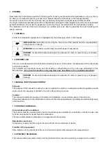
4. HANDLING AND TRANSPORT
The appliance is supplied complete with all its parts in a special closed packaging that is fixed with straps to a
wooden platform (pallet).
The oven must be unloaded and handled by a qualified forklift operator.
To transport the oven to the installation site, use a wheeled
trolley with a suitable capacity.
When lifting, avoid tearing the packaging or sudden
movements.
Make sure that the lifting equipment has a load-bearing
capacity greater than the weight of the load to be lifted.
The lifting equipment operator will be fully responsible for
lifting the loads.
The oven must be installed by qualified personnel in
accordance with the local, national and European
regulations.
Make sure that the oven’s support surface has an adequate
load-bearing capacity and is level.
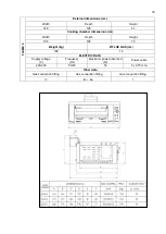
After the oven has been removed from its special packaging, position it where desired whilst taking into account
the minimum safety distances from walls and/or other appliances.
Keep a distance of at least
25 cm
between the oven and the room’s side walls, an
d where possible, leave at
least
50 cm
on the right side so that the electrical system can easily be accessed for maintenance and/or repairs.
Leave a gap of at least
50 cm
from the back wall.
m
Make sure that children do not play with the packaging components (e.g. film and
polystyrene).
Suffocation hazard!
5. PREPARING THE INSTALLATION SITE
5.1 SAFETY PRECAUTIONS
!
Any works carried out in the location of the appliance, is and remains the responsibility of the
user. The latter is also responsible for carrying out checks on the proposed installation solutions.
The user must comply with all local, national and European safety regulations.
The appliance must be installed on floors with an adequate load-bearing capacity.
The appliance’s assembly and
disassembly instructions are reserved for specialised technicians only.
We recommend that users always contact our support service for any requests they may have for the qualified
technicians.
Before starting the appliance’s assembly or disassembly procedu
re, the installer must comply with the safety
precautions required by law, and the following in particular:
He/she must not operate in adverse conditions;
The installer must operate in perfect psychophysical conditions and must check that the individual and
personal safety devices are intact and fully functional;
He/she must wear safety gloves;
He/she must wear safety shoes;
He/she must use electrically-insulated tools;
He/she must make sure that there are no obstacles in the assembly/disassembly area.
Summary of Contents for CHFPG4
Page 2: ...2...
Page 14: ...14 3 3 Schemi elettrici...
Page 15: ...15...
Page 47: ...47 3 3 Sch mas de c blage...
Page 48: ...48...
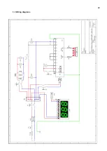
Page 80: ...80 3 3 Wiring diagrams...
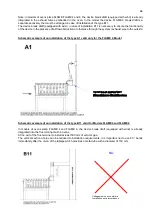
Page 81: ...81...
Page 102: ...102 RU Category II2H3 Type of installation FLAME4 A1 B11 B21 FLAME 6 9 B11 B21...
Page 104: ...104 7 6 131 7 7 132 8 132 8 1 132 8 2 132 8 2 1 132 8 2 2 132 8 3 132 9 133 10 134...
Page 105: ...105 1 1 1 m 1 2 m 1 3 1 4...
Page 108: ...108 1 11 1 12 1 13 CE CE...
Page 109: ...109 RU 1 14 2 2 1...
Page 110: ...110 2 2 2 3...
Page 112: ...112 FLAME 9 148 126 47 105 105 15 196 18 220 230 50 60 50 3 x 0 75 2 B11 B21 I...
Page 113: ...113 3 3...
Page 114: ...114...
Page 116: ...116 4 25 50 50 m 5 5 1...
Page 117: ...117 5 2 25 50 50 6 6 1 4 2 F 6 2 6 2 1 3...
Page 118: ...118 6 2 1 1 6 2 2 1 13 1 5 6 2 3 A1 B11...
Page 119: ...119 B21 FLAME 4 FLAME 6 FLAME 9 B11 B11 A1 FLAME 4...
Page 123: ...123 FLAME 4 FLAME 6 45 6 2 4 6 3 1 EV1 2 EV2 3 Pin 4 Pout 5 6...
Page 124: ...124 1 0 1 E 2 3 Pin 6 7 3 Pin 3 4 Pout 4 B MAX 10 5 B MIN C D 6x1 E...
Page 130: ...130 A B C D E F G H 7 2 200 C 1 8 300 350 C 7 3 200 C A 1 D B 0 B 1 7 4...
Page 131: ...131 7 5 380 C 3 3 5 1 30 40 380 2 3 4 5 B 0 B 1 20 7 6 H 1...
Page 132: ...132 7 7 D 0 A 0 8 8 1 89 391 8 2 8 2 1 350 60 100 C 8 2 2 8 3...
Page 133: ...133 9 0 1 1 PF Schuko...
Page 134: ...134 10 13 151 25 2005 2002 95 2002 96 2003 108...
Page 146: ...146 3 3 Esquemas el ctricos...
Page 147: ...147...
Page 179: ...179 3 3 Schaltpl ne...
Page 180: ...180...
Page 201: ...201 EXPLODED VIEW DRAWINGS AND SPARE PARTS...
Page 202: ...202...
Page 203: ...203...
Page 209: ...209 ROTATING DOOR SYSTEM LAMP SYSTEM...
Page 210: ...210 ANALOGUE THERMOMETER CONTROLS DIGITAL THERMOMETER CONTROLS...
Page 211: ...211...


