background image


C

OLLOID 

M

ILL 

I. O. & M


19 

3.0 Setting  Zero 

3.1  Turn dial  in bot h directions ensuri ng that m ovement 

stops at the point where lock  screws were tightened and 

that there is no “rubbi ng” or draggi ng when shaft is 

turned by hand.  Repeat sect ion 2.0 if any rotor/stator 

“rubbing” occurs. 

3.2  Remove the window frame and the small window


covering the index ring. 

3.3  Undo the three (3) screws on the dial index ring 
3.4  Align the zero on the index ring with the arrow/indicator 

on the housing. 

3.5  Retighten the three (3) screws 
3.6  Replace the window. 
 

4.0 Testing  Zero 

4.1  Test the machine setting at zero by turning by hand and 

ensuring that there is no rubbing 


5.0  Replace Coupling and Operate 

 
N

OTES ON 

M

ACHINE 

R

EBUILDS


As you make com ponent changes to  the equipment, be aware of the


following: 

• 

If the rotor and stator have been  replaced, the m ill will need to be 

recalibrated. See preceding procedures. 

• 

Use caution to be sure that o-ri ngs have not been “pinched” when  

placing stator within the stator housing.  

• 

Before operating, be certain that th e shaft operates freely at t he zero 

gap setting. 

Summary of Contents for Greerco

Page 1: ......

Page 2: ......

Page 3: ...TION 5 SHAFT SEALING METHOD 5 COLLOID MILL ELASTOMERS SEALS O RINGS 6 JACKETED STATOR HOUSING 7 PRODUCT PROCESSING GUIDELINES 7 DAILY MAINTENANCE CLEANING 8 3 WAY VALVE MAINTENANCE CLEANING 9 RECOMMENDED LUBRICANTS 9 COLLOID MILL EXPLODED VIEW W250H B EXAMPLE 9 COLLOID MILL DISASSEMBLY 10 COLLOID MILL RE ASSEMBLY 12 GAP SETTING CALIBRATION 17 NOTES ON MACHINE REBUILDS 19 SPARE PARTS 20 ...

Page 4: ...on test runs PRINCIPLE OF OPERATION Like most high shear devices the Greerco Colloid Mill employs a high speed rot or runni ng in close proxim ity to a fi xed stator to perform its shearing operation In this colloid m ill the gap between the rotor and stator is adjusta ble Product is processe d as it passes t hrough t he shear zone where intense hydraulic and shear forces result in a product that ...

Page 5: ...tory zero was a 0 003 0 005 gap setting Your machine is configured to prevent against metal to metal contact MOUNTING CONFIGURATION A Greerco Colloid Mill is available in one of two configurations horizontal or vertical There is no difference in the milling head or mixing processes in these configurations merely the machine s orientation Horizontal Configuration H Model Designation If you have pur...

Page 6: ... with a 230 460V 3φ 60Hz explosion proof motor with a nominal speed of 3600rpm ALL WIRING SHOULD BE COMPLETED BY A QUALIFIED ELECTRICIAN FAMILIAR WITH THIS MOTOR ITS ENVIRONMENT AND ITS INTENDED FUNCTION Consult motor nameplate to confirm act ual specifications of the m otor on your mill Motor wiring diagram is located within the motor conduit box or on the motor nameplate See the next section for...

Page 7: ...drawing at the back of this manual for confirmation of the scope of your machine Double Lip Seal All Greerco Colloid Mills are stocked at the factory in a double lip seal configuration The lip seals used are m ultiple layer radial shaft seals consisting of a Teflon anti friction element an d a fluoroelastomer sealing element bonded to a metal shell Single Mechanical Seal A standard factory option ...

Page 8: ... require alte rnate materials we would be happy to source these components for you Shaft Seals See above section detailing shaft sealing options Should your seal leak you will see process material discharge from the weep hole located in the underside of the mill housing Seals should be replaced at the first sign of leakage or more costly failures may result O Rings Your colloid m ill is equipped w...

Page 9: ...your colloi d m ill Tram p meta l or rigid sol ids m ay severely damage the mixing head and its components When determ ining the appropriate gap setting the m ill should be started at a fairly open gap setting approximately 30 on the indicator dial The gap should then be gradually decreased until a suitable sample is obtained Some applications will require the product to be recycled to achieve the...

Page 10: ... emulsions will only require a hot water rinse With the m ill operating the gap should be op ened and closed several tim es to dislodge any material buildup around the seals More severe materials such as o ils waxes and greases may require a detergent and hot water rinse Materials such as oil paints inks and pigment dispersions may require a solvent rinse If solvents are used it is esse ntial that...

Page 11: ...tone to prevent scoring t he body a nd eventual leakage Valve bodies and plugs are mated during manufacture and must not be interchange d with parts of other valves Each body and matching plug is identified with identical numbers COLLOID MILL LUBRICATION Motor Follow motor m anufacturer s guidelines for proper m otor maintenance Bearings All mill bearings are of the shielded type and are packed in...

Page 12: ...m ill head retract the swing bolts and remove the cover plate NOTE Stator housing is now loose If you are working on a horizontal unit do not allow stator housing to fall Lay the mill head plate on flat surface to prevent damage to the OD of the plate 3 The stator housing assem bly can now be lifted out of the mill Complete disassembly of the stator housi ng and stator assembly is not necessary fo...

Page 13: ...k of this manual for part identification a Remove the m ill from the base by loosening the lower nut on the front support stud under the base plate and rem oving the four nuts that secure the lower support to the housing support b Remove the coupling ha lf from the m otor end of the shaft It is now possible to support the m ill on wooden blocks for stability during the rebuild procedure as needed ...

Page 14: ...earings from the shaft 9 Further disassem bly is not required for sta ndard maintenance Gear housi ng and adjustm ent gearing failures are not typical Shoul d you need to disassem ble the shaft adjustmen t gearing please con sult the factory for guidance COLLOID MILL RE ASSEMBLY Reassembly may be completed by reversing the above procedure 1 Shaft Bearing and Bearing Housing Configuration a There a...

Page 15: ...g is well seated in the groove provided i Replace the slinger on threaded end of shaft with flat side ou t and it sits against the bearing housing j Thread the large locknut ont o the m ill end of shaft until it bottoms out Once secure the assembly is now a single component 2 Replace the Gap Setting Adjustment Nut a Adjustment Nut is the large bronze gear with a threaded ID and the red numbered in...

Page 16: ...e key in bearing housing keyway b Lower support is t he cast iron com ponent that resem bles a flange and mates directly to the bottom of the housing c Grease the ID of the lower support d Place a bead of silicon sealant around the edge of the housing and boltholes e Align low er support key way with key and Sli de the lower support down over t he shaft and bearing housing i nsuring that all edges...

Page 17: ...reated as a single item Should the gears need replacing consult the factory for information on factory rebuild services or advice on how to proceed a Be sure that the hand wheel and gear assembly spins freely b Place a bead of silicon sealan t around the edge of the square opening on the m ill housing lower support assembly where the adjustment nut gear is exposed c Align the gear housing hand whe...

Page 18: ...ded Do not st retch the o ring to fit the oute r edge of the seal plate merely la y it on the out er most section of the seal plate face iv Secure plate in place w ith the three locking screws provided b Mechanical Seal Configuration i Press the stationary seal face into the seal plate ii Slide seal plate down over shaft iii Replace the seal plate o ring around OD of plate in groove provided iv Se...

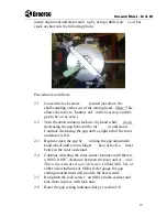
Page 19: ...1 0 Getting Started 1 1 Disconnect the electricity to the unit 1 2 Rem ove Coupling Guard 1 3 Disconnect Motor Coupling so Shaft may be Turned by Hand 1 4 Turn Gap Setting Dial to Zero 1 5 Remove Inlet Cap and Visually Inspect Rotor and Stator 2 0 Findi ng Zero When the zero is set at the factory a dial indicator is placed on the shaft to ensure that t here is a 0 003 0 005 gap between the rotor a...

Page 20: ...Continue decreasing the gap until a slight rub of the rotor and stator is felt 2 3 Begin to open the gap by turning the gap adjustment hand wheel until you no longer hear or feel co ntact between the rotor and stator 2 4 Continue widening the rotor stator clearance until there is a 0 003 0 005 clearance between the rotor and st ator This is theoretical zero on a Greerco Colloid Mill Use of either ...

Page 21: ...g with the arrow indicator on the housing 3 5 Retighten the three 3 screws 3 6 Replace the window 4 0 Testing Zero 4 1 Test the machine setting at zero by turning by hand and ensuring that there is no rubbing 5 0 Replace Coupling and Operate NOTES ON MACHINE REBUILDS As you make com ponent changes to the equipment be aware of the following If the rotor and stator have been replaced the m ill will ...

Page 22: ...t Elastomer Kits Available for all lip seal configurations this kit contains all machine o rings and required lip seals Consumable Spares Kit Available for any shaft seal configura tion this kit contai ns all o rings bearings shaft seals and retaining ri ng Please specify machine serial number at time of quote order Complete Machine Rebuild Kit Available for any shaft seal configuration this kit c...

Reviews: