background image


System utilities  71 

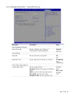
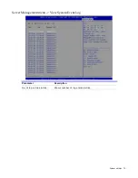
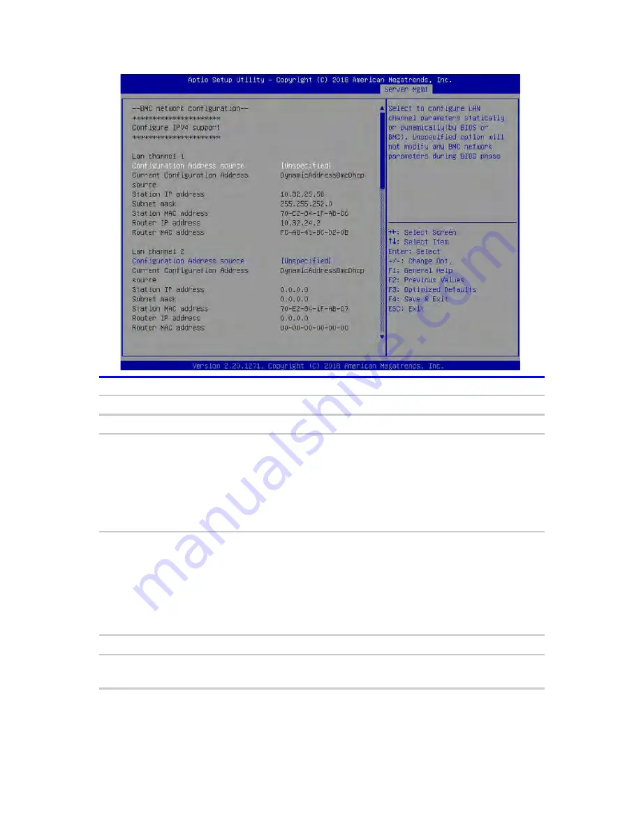
Server Management menu -> BMC Network Configuration   

Parameter 

Description 

Value 

BMC network configuration 


Configure IPV4 support 


Configuration Address source    Select to configure LAN channel parameters 

statically or dynamically (by BIOS or BMC). 

Unspecified option will not modify any BMC 

network parameters during BIOS phase. 

Unspecified 
Static 
Dynamic 

BMC DHCP 
Dynamic 

BMC 

Non-DHCP 

Current Configuration Address 

source 
Station IP address 
Subnet mask 
Station MAC address 
Router IP address 
Router MAC address 

Shows the IPV4 configuration information. 

Configure IPV6 support 


IPV6 Support 

Enable or disable LAN IPV6 support. 

Enabled 
Disabled 

Summary of Contents for RB133 1U

Page 1: ...RB133 1U Server RB133G13 U10 User Manual August 2019 Version 1 1 A document provides an overview of product features functions architecture and support specifications...

Page 2: ...and is not responsible for information outside the Chenbro Micom Co Ltd website Microsoft Windows and Windows Server are either registered trademarks or trademarks of Microsoft Corporation in the Unit...

Page 3: ...an locations 12 DIMM slot locations 13 Status LED indicators 14 Front panel LED indicators 14 Rear panel LED indicators 15 Serial label pull tab 16 Operations 17 Power down the server 17 Using Power C...

Page 4: ...ations de s curit 84 Preventing electrostatic discharge 84 Symbols on equipment 84 Warnings and cautions 85 Preparation procedures 86 2 5 HDD SSD storage 86 Power supply 91 PCIe interposer card 93 Ris...

Page 5: ...g 133 Cabling overview 133 10 CH NVMe BPB to MB PCIe Gen 3 134 10 CH NVMe BPB to MB I2C 135 Front I O Board 135 Specifications 136 Environmental specifications 136 Server specifications 136 System rat...

Page 6: ...2 5 NVMe SSD slot 10 2 2 5 NVMe SSD slot 8 3 2 5 NVMe SSD slot 6 4 2 5 NVMe SSD slot 4 5 2 5 NVMe SSD slot 2 6 Power button LED 7 UID button 8 USB 2 0 ports 9 2 5 NVMe SSD slot 1 10 2 5 NVMe SSD slot...

Page 7: ...ion Item Description 1 Redundant power supply unit 2 2 Redundant power supply unit 1 3 RJ45 for BMC management LAN 4 PCIe add on card 5 Rear UID button LED 6 1G 10G LAN port 1 7 1G 10G LAN port 2 8 US...

Page 8: ...board 1 4 System fan 6 5 RTC battery 1 6 7 M 2 SSD 2 8 PCIe interposer card 1 9 Mainboard 1 10 PCIe add on card 1 support low profile PCIe add on cards using standard bracket only 11 Riser card 1 12...

Page 9: ...CPU2 storage connector 6 CPU1 8 pin ATX power connector 18 CPU2 storage connector 7 DIMM D1 D2 E1 F1 slots 19 CPU2 storage connector 8 CPU1 storage connector 20 Front board USB2 signals connector 9 DI...

Page 10: ...or 3 PCIe signal connector 4 PCIe signal connector 5 PCIe signal connector 6 PCIe signal connector 7 Sideband signal connector 8 PCIe signal connector 9 BPB power connector 10 PCIe signal connector 11...

Page 11: ...ur 11 Fan control board components Item Description 1 Sideband signal connector 2 Fan 1 connector 3 Fan 2 connector 4 Fan 3 connector 5 Fan 4 connector 6 Fan 5 connector 7 Fan 6 connector 8 Fan power...

Page 12: ...System Tour 12 Fan locations Item Description 1 Fan 1 2 Fan 2 3 Fan 3 4 Fan 4 5 Fan 5 6 Fan 6...

Page 13: ...ssor numbered sequentially from 1 to 6 Item Description Item Description A1 CPU1 DIMM Slot 1 G1 CPU2 DIMM Slot 1 A2 CPU1 DIMM Slot 2 G2 CPU2 DIMM Slot 2 B1 CPU1 DIMM Slot 3 H1 CPU2 DIMM Slot 3 C1 CPU1...

Page 14: ...2 HDD cage activity indicator Off Green Red solid Red 4Hz blinking Red 1Hz blinking HDD not active HDD is active HDD error Locate Re build 3 System Power Off Blue Blue blinking System is off No AC po...

Page 15: ...ailure AC cord unplugged No AC power 3 NIC Link left Off Yellow blinking No connection Linked and activity on the network 4 NIC Link right Off Green Amber Yellow No connection Linked to 100Mbps networ...

Page 16: ...our 16 Serial label pull tab The serial label pull tab contains important information about the server like the BMC username and password To access the serial tab A Pull the serial label tab from the...

Page 17: ...server to enter standby mode without properly exiting applications and the OS If an application stops responding you can use this method to force a shutdown Use a virtual power button selection throug...

Page 18: ...te locations Wistron BMC management is a powerful tool that provides multiple ways to configure update monitor and repair servers remotely BMC Standard comes preconfigured on Wistron servers without a...

Page 19: ...ions 19 To check the current firmware version that is installed in your server from the BMC menu bar click Maintenance Firmware Information The current firmware information will be displayed Firmware...

Page 20: ...s les widgets en mode de mise jour les autres pages Web et services ne fonctionneront pas Tous les widgets ouverts seront ferm s automatiquement Si le processus de mise niveau est annul au milieu des...

Page 21: ...Operations 21 1 Click Preserve all Configuration to preserve all configuration You can also customize which configuration is retained by clicking the Edit Preserve Configuration option...

Page 22: ...ill be displayed for http https but in the case of TFTP files the file is automatically uploaded displaying the status of upload 3 Click Start firmware update to start the firmware update A pop up win...

Page 23: ...fois dans les widgets en mode de mise jour les autres pages Web et services ne fonctionneront pas Tous les widgets ouverts seront ferm s automatiquement Si le processus de mise niveau est annul au mi...

Page 24: ...p window for uploading file will be displayed for http https but in the case of TFTP files the file is automatically uploaded displaying the status of upload 3 Click Start firmware update to start the...

Page 25: ...proc dure d installation de retrait ou de remplacement Une mise la terre incorrecte peut provoquer une d charge lectrostatique CAUTION Do not operate the server with the top cover open or removed Ope...

Page 26: ...de les toucher CAUTION To prevent damage to electrical components take the appropriate anti static precautions before beginning any installation removal or replacement procedure Improper grounding ca...

Page 27: ...he front of the server until it latches into place 2 Use two 2 screws to secure the front top cover to the chassis B Install the rear top cover 1 Place the rear top cover on top of the server and slid...

Page 28: ...ess and release the Power On Standby button When the server goes from the standby mode to the full power mode the system power LED changes from off to solid green Powering on and selecting boot option...

Page 29: ...fore POST is completed you will need to restart the server E Use the Left Right arrow keys to move between the menu screens then press Enter to view that menu tab F Use the Up Down arrow keys to move...

Page 30: ...all possible entries A parameter that is enclosed in square brackets is user configurable Black font parameters are not user configurable for one of the following reasons The field value is auto conf...

Page 31: ...ption BIOS Information BIOS Vendor Copyright owner of BIOS software Project Version Official project version code of the server BIOS Build Date and Time Date when the system BIOS was built Access Leve...

Page 32: ...iption Total Memory Size of system memory detected during boot up Usable Memory Size of system memory that can be used by server System Language Sets the system language System Date Sets the system da...

Page 33: ...Synchronize BIOS time with the configuration CSM Configuration CSM configuration Enable Disable Option ROM execution settings etc NVMe Configuration NVMe Device Options Settings Network Stack Configu...

Page 34: ...ced menu Trusted Computing Parameter Description Value Configuration Security Device Support Enable Disable Security Device NOTE Your Computer will reboot during restart in order to change State of th...

Page 35: ...System utilities 35 Advanced menu SMART Settings Parameter Description Value SMART Self Test Run SMART Self Test on all HDDs during POST Enabled Disabled...

Page 36: ...e computer which the user is using will exchange data Both computer should have the same or compatible setting Legacy Console Redirection Settings Legacy Console Redirection Settings Console Redirecti...

Page 37: ...0 ASCII char set VT100 Extends VT100 to support color function keys etc VT UTF8 Uses UTF8 encoding to map Unicode chars onto 1 or more bytes ANSI Extended ASCII char set VT100 VT100 VT UTF8 ANSI Bits...

Page 38: ...y require more than 1 stop bit 1 2 Flow Control Flow control can prevent data loss from buffer overflow When sending data if the receiving buffers are full a stop signal can be sent to stop the data f...

Page 39: ...display redirection of Legacy OS and Legacy OPROM messages COM0 COM1 Resolution Select the Number of Rows and Columns supported in redirection on Legacy OS 80x24 80x25 Redirect After POST When Bootlo...

Page 40: ...UTF8 encoding to map Unicode chars onto 1 or more bytes ANSI Extended ASCII char set VT100 VT100 VT UTF8 ANSI Bits per second Selects serial port transmission speed The speed must be matched on the ot...

Page 41: ...age Class Display Class Other Devices Shows current parameters of Device Group default ROM Policy On Board Mass Storage Controller Enable Disable the onboard mass storage controller Enabled Disabled O...
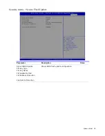
Page 42: ...cription Value PCI Driver Version Shows AMI PCI Driver Version information PCI Devices Common Settings Above 4G Decoding Globally Enable or Disable 64bit capable devices to be decoded on Above 4G addr...

Page 43: ...GMT Shows information about the system s Time Zone NTP Server IP IPv4 Shows information about the NTP Server IP IPv4 Synchronize Time Time is synchronized with the NTP Server IP IPv4 NTP Server IP IPv...

Page 44: ...OS reaction on INT19 trapping by Option ROM Immediate execute the trap right away Postponed execute the trap during legacy boot Immediate Postponed Boot option filter This option controls Legacy UEFI...

Page 45: ...escription Value Video Controls the execution of UEFI and Legacy Video OP ROM Do not launch UEFI Legacy Other PCI devices Determines OP ROM execution policy for devices other than Network Storage or V...

Page 46: ...Advanced menu NVMe Configuration Parameter Description NVMe Configuration No NVME Device Found Shows information about NVMe device installed NOTE This information will only show when Storage OP ROM is...

Page 47: ...is set to Enabled Enabled Disabled Ipv6 PXE Support Enable Ipv6 PXE Boot Support If disabled IPV6 PXE boot option will not be created NOTE This information will only show when Network Stack is set to...
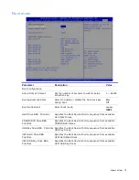
Page 48: ...rmat is accepted Range is from 4 to 223 Add an Attempt Add an attempt Delete Attempt Delete one or more attempts Change Attempt Order Change the order of Attempts using keys Use arrow keys to select t...

Page 49: ...l R VROC with VMD Technology Shows Intel R VROC with VMD Technology Version information No RAID volumes on the system Shows information about RAID volumes installed in the system No Intel VMD Controll...

Page 50: ...ntel R VROC with VMD Technology Intel R DCPMEM Driver Broadcom Gigabit Ethernet Driver Broadcom Gigabit Ethernet Driver Provides Health Status for the Drivers Controllers NOTE Information shown on thi...

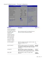
Page 51: ...System utilities 51 Chipset menu Parameter Description PCH Configuration PCH Configuration settings...

Page 52: ...PCH Configuration Parameter Description PCH Configuration PCH Devices Intel R IO Controller Hub devices settings PCH SATA Configuration SATA Device Configuration settings PCH sSATA Configuration s SA...

Page 53: ...3 PCH Configuration PCH Devices sub menu Parameter Description Value PCH state after G3 Specify what state to go to when power is re applied after a power failure G3 state S0 State S5 State Leave powe...

Page 54: ...System utilities 54 PCH Configuration SATA Configuration sub menu Parameter Description Value PCH SATA Configuration Configure SATA as Select an operating mode for the SATA device AHCI RAID...

Page 55: ...System utilities 55 PCH Configuration sSATA Configuration sub menu Parameter Description Value PCH sSATA Configuration Configure sSATA as Select an operating mode for the sSATA device AHCI RAID...

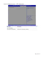
Page 56: ...ion Processor Configuration settings Common RefCode Configuration Common RefCode Configuration settings UPI Configuration UPI Configuration settings Memory Configuration Memory Configuration settings...

Page 57: ...sor Shows Per Socket Configuration settings CPU core Enabled Select the number of processor cores to enable and make available for use 0 All 0 1 5 Hyper Threading Enable or disable processor core virt...

Page 58: ...System utilities 58 Socket Configuration menu Common RefCode Configuration Parameter Description Value Numa Enable or Disable Non Uniform Memory Access NUMA Enabled Disabled...

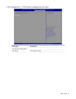
Page 59: ...System utilities 59 Socket Configuration menu UPI Configuration Parameter Description UPI Configuration UPI General Configuration UPI General Configuration settings...

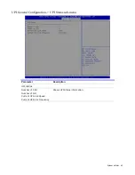
Page 60: ...System utilities 60 UPI Configuration UPI General Configuration sub menu Parameter Description UPI General Configuration UPI Status UPI Status settings...

Page 61: ...tem utilities 61 UPI General Configuration UPI Status sub menu Parameter Description UPI Status Number of CPU Number of IIO Current UPI Link Speed Current UPI Link Frequency Shows UPI Status informati...

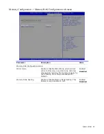
Page 62: ...sable Plan Of Record restrictions for DDR4 frequency and voltage programming Enable Enforces this feature Disable Disables this feature Auto Sets it to the MRC default setting current default is Enabl...

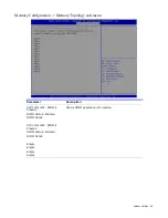
Page 63: ...uration Memory Topology sub menu Parameter Description CPU1 DimmA1 DIMM is Present DIMM Status Enabled DIMM Detail CPU1 DimmB1 DIMM is Present DIMM Status Enabled DIMM Detail Empty Empty Empty Empty S...

Page 64: ...tup Mirror mode Enable or Disable Mirror Mode which will set entire 1LM memory in system to be mirrored consequently reducing the memory capacity by half Enabling Mirror Mode will disable XPT Prefetch...

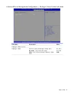
Page 65: ...menu Advanced Power Management Configuration Parameter Description Advanced Power Management Configuration CPU P State Control CPU P State Control Configuration settings Package C State Control Packag...

Page 66: ...to enable the Intel SpeedStep Technology NOTE After enabling IST in BIOS Setup you need to enable it on your operating system as well Consult your OS documentation for related instructions Enabled Di...

Page 67: ...nfiguration Package C State Control sub menu Parameter Description Value Package C State Control Package C State Set the maximum Package C State Limit No Limit Set to No Limit value Auto Set to the ma...

Page 68: ...MC Firmware Revision information IPMI Version Shows IPMI Version information BMC Interface s Shows BMC device interface s information System Event Log Press Enter to change the System Event Log config...

Page 69: ...Erase Settings Erase SEL Choose options for erasing SEL No Yes When SEL is full Choose options for reactions to a full SEL Do Nothing Erase Immediately Custom EFI Logging Options Log EFI Status Code S...

Page 70: ...er Description FRU Information System Manufacturer System Product Name System Version System Serial Number Board Manufacturer Board Product Name Board Version Board Serial Number Chassis Manufacturer...

Page 71: ...lly or dynamically by BIOS or BMC Unspecified option will not modify any BMC network parameters during BIOS phase Unspecified Static Dynamic BMC DHCP Dynamic BMC Non DHCP Current Configuration Address...

Page 72: ...amically by BIOS or BMC Unspecified option will not modify any BMC network parameters during BIOS phase Unspecified Static Dynamic BMC DHCP Dynamic BMC Non DHCP Current Configuration Address source St...

Page 73: ...System utilities 73 Server Management menu View System Event Log Parameter Description No of log entries in SEL Shows number of log entries in SEL...

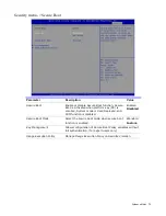
Page 74: ...assword Set the administrator s password User Password Set the user s password HDD Security Configuration HDD Security Configuration for selected drive Secure Boot Select to configure the secure boot...

Page 75: ...enrolled System mode is User Deployed and CSM function is disabled Enabled Disabled Secure Boot Mode Select the secure boot mode when secure boot function is enabled Standard Custom Key Management All...

Page 76: ...ry Keys Force System to User Mode Install factory default Secure Boot key databases Reset to Setup Mode Delete all Secure Boot key databases from NVRAM Platform Key PK Enroll Factory Defaults or load...

Page 77: ...ption ROM Image Execution Policy per device path on Security Violation Query User Deny Execute Removable Media Image Execution Policy per device path on Security Violation Query User Deny Execute Fixe...

Page 78: ...ies 78 Security menu Secure Flash Update Parameter Description Value Signed BIOS Update FW Key Type FW Key Name FW Update Method FW Rollback Protection Flash Write Protection Shows BIOS flash update c...

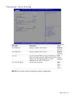
Page 79: ...ities Specifies the Boot Device Priority sequence from available Hard Disk Drives CDROM DVD Drive BBS Priorities Specifies the Boot Device Priority sequence from available CDROM DVD Drives USB Key Dri...

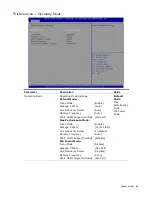
Page 80: ...System utilities 80 Wistron menu Parameter Description Operating Mode Operating Mode settings Device IO Setting Device IO Option Settings...

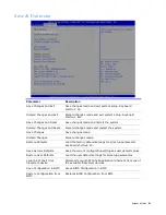
Page 81: ...Frequency Auto PCI E ASPM Support Global Per Port Max Performance Mode Turbo Mode Enable Package C State C0 C1 state Link Frequency Select 10 4GB s Memory Frequency Auto PCI E ASPM Support Global Dis...

Page 82: ...le the M 2 Slot 2 Enabled Disabled Slot 1 4 In auto mode the BIOS will remove the EXP port if there is no device or errors on that device and the device is not HP capable Disable is used to disable po...
Page 83: ...Save changes made Discard Changes Discard changes made Restore Defaults Load the factory default settings for all setup parameters Keyboard shortcut F3 Save as User Defaults Save the current configura...

Page 84: ...of the precautions you must follow when setting up the system or handling parts A discharge of static electricity from a finger or other conductor may damage mainboards or other static sensitive devic...

Page 85: ...y from a hot component allow the surface to cool before touching AVERTISSEMENT Pour r duire le risque de blessure par un composant chaud laissez sa surface refroidir avant de la toucher 12 92 kg 28 48...

Page 86: ...ck in this manner results in improper airflow and improper cooling that can lead to thermal damage MISE EN GARDE N utilisez pas le bac trop longtemps si le panneau d acc s est ouvert ou enlev Une tell...

Page 87: ...ove the component A Remove the storage assembly from the chassis 1 Press the release latch to disengage the storage assembly from the chassis 2 Pull the latch handle to disengage the storage assembly...

Page 88: ...1 Bottom up the HDD tray and face the side without a concave slot of HDD tray as shown 2 Press your 2 thumbs on the HDD as shown Notice please operate this on a stable surface in case the HDD dropping...

Page 89: ...mponent A Install the 2 5 HDD SSD 1 Slide in the HDD until align the anchor point of HDD tray 2 Push down the HDD when it is secured with a click B Install the 2 5 HDD SSD storage assembly 1 Insert th...

Page 90: ...System upgrades 90 2 Push the latch until the storage assembly locks into place...

Page 91: ...coup es Manque de proc der de la sorte entra nera un coulement d air inad quat pouvant entra ner des dommages thermiques To remove the component A Power down the server Link B Disconnect all peripher...

Page 92: ...System upgrades 92 To replace the component A Install the power supply 3 Push the new power supply into the power bay until it locks into place...

Page 93: ...es sur une surface de travail antistatique ou dans des sacs antistatiques s par s CAUTION To prevent damage to electrical components take the appropriate anti static precautions before beginning any i...

Page 94: ...securing the PCIe interposer card to the bracket 2 Detach the PCIe interposer card from the bracket To replace the component A Install the PCIe interposer card 1 Place the PCIe interposer card into th...

Page 95: ...interposer card assembly 1 Place the PCIe interposer card assembly into the mainboard and push it down until it latches into place 2 Use one 1 screw to secure the PCIe interposer card bracket to the m...

Page 96: ...nts sensibles l lectricit statique de la carte m re d faillante placez les sur une surface de travail antistatique ou dans des sacs antistatiques s par s CAUTION To prevent damage to electrical compon...

Page 97: ...embly 1 Remove one 1 screw securing the PCIe add on card bracket to the riser card assembly 2 Detach the PCIe add on card from the riser card F Remove the riser card 1 Remove the two 2 screws securing...

Page 98: ...secure the riser card to the bracket B Remove the EMI shielding from the riser card assembly 1 Detach the EMI shielding from the riser card assembly NOTE When installing a PCIe add on card for the fir...

Page 99: ...ser card and push until it latches into place 2 Use one 1 screw to secure the PCIe add on card bracket to the riser card assembly D Install the riser card assembly 1 Place the riser card assembly into...

Page 100: ...ur r duire les risques de blessures caus s par des surfaces chaudes laissez les disques et les composants internes du syst me refroidir avant de les toucher To remove the component A Power down the se...

Page 101: ...he air baffle 1 Place the air baffle into its slot as shown To avoid damage to the air baffle make sure that the air baffle edge does not get stuck in between the latch of the power cable B Install th...

Page 102: ...is accessed while writing to or reading from the memory A dual rank DIMM is similar to having two single rank DIMMs on the same module with only one rank accessible at a time A quad rank DIMM is effec...

Page 103: ...Mixing of non 3DS and 3DS LRDIMMs is not allowed in the same channel across different channels and across different sockets Mixing of AEP DIMMs with RDIMMs is supported in Purley platform Mixing of A...

Page 104: ...times For RAS modes that require matching DIMM populations the same slot positions across channels must hold the same DIMM type with regards to size and organization DIMM timings do not have to match...

Page 105: ...nel Mode must be populated identically with regards to size and organization DIMM slot populations within a channel do not have to be identical but the same DIMM slot location across Channel 0 Channel...

Page 106: ...4 GB 8 GB 16 GB 2 Rank 1R Single rank 2R Dual rank 4R Quad rank 8R Octal Rank 3 Data width on DRAM X4 4 bit X8 8 bit 4 Memory generation PC4 DDR4 5 Maximum memory speed 2667 MT s 6 CAS latency P 16 7...

Page 107: ...carte m re d faillante placez les sur une surface de travail antistatique ou dans des sacs antistatiques s par s CAUTION To prevent damage to electrical components take the appropriate anti static pre...

Page 108: ...e the component A Install the DIMM 1 Insert the DIMM into its slot 2 Press the DIMM down until the holding clips latch into place B Install the air baffle Link C Install the riser card assembly Link D...

Page 109: ...s composants sensibles l lectricit statique de la carte m re d faillante placez les sur une surface de travail antistatique ou dans des sacs antistatiques s par s CAUTION To prevent damage to electric...

Page 110: ...uring the M 2 22110 SSD module to the mainboard 2 Detach the M 2 22110 SSD module from the mainboard To replace the component A Install the M 2 22110 SSD module 1 Insert the M 2 22110 SSD module into...

Page 111: ...ink M 2 2280 SSD Module To replace the component A Power down the server Link B Disconnect all peripheral cables from the server C Remove the top covers Link D Remove the riser card assembly Link E Re...

Page 112: ...nboard To remove the component A Power down the server Link B Disconnect all peripheral cables from the server C Remove the top covers Link D Remove the riser card assembly Link E Remove the air baffl...

Page 113: ...System upgrades 113 G Relocate the screw lock in the mainboard as shown H Install the air baffle Link I Install the riser card assembly Link J Install the top covers Link...

Page 114: ...urfaces chaudes laissez les disques et les composants internes du syst me refroidir avant de les toucher To remove the component A Power down the server Link B Disconnect all peripheral cables from th...

Page 115: ...e heatsink from the mainboard To replace the component A Install the heatsink 1 Place the heatsink into the mainboard NOTE Before replacing the heat sink clean the top surface of the CPU then apply a...

Page 116: ...6 2 Tighten the four 4 captive screws to secure the heatsink to the mainboard Follow the screw sequence indicated below B Install the air baffle Link C Install the riser card assembly Link D Install t...

Page 117: ...r inside separate antistatic bags MISE EN GARDE Pour ne pas provoquer de d charges lectrostatiques pouvant causer des dommages lorsque vous retirez des composants sensibles l lectricit statique de la...

Page 118: ...1 Disengage the retaining clips securing the processor assembly to the heatsink 2 Detach the processor assembly from the heatsink H Remove the processor 1 Press both ends of the carrier to disengage t...

Page 119: ...lace B Install the processor assembly 1 Place the heatsink into the processor assembly making sure the retatining clips are properly aligned with their sockets and press it down until it latches into...

Page 120: ...urfaces chaudes laissez les disques et les composants internes du syst me refroidir avant de les toucher To remove the component A Power down the server Link B Disconnect all peripheral cables and pow...

Page 121: ...all the fan module 1 Insert the fan module into its slot and press it down until it latches into place 2 Connect the fan cable to the fan control board B Install the air baffle Link C Install the rise...

Page 122: ...sensibles l lectricit statique de la carte m re d faillante placez les sur une surface de travail antistatique ou dans des sacs antistatiques s par s CAUTION To prevent damage to electrical components...

Page 123: ...System upgrades 123 G Remove the fan control board from the chassis 1 Remove the two 2 screws securing the fan control board to the chassis 2 Detach the fan control board from the chassis...

Page 124: ...rol board 1 Place the fan control board into the chassis 2 Use two 2 screws to secure the fan control board to the chassis B Connect all cables to the fan control board C Install the air baffle Link D...

Page 125: ...s higher than 70 C 158 F Do not disassemble crush puncture short external contacts or dispose of in fire or water Replace only with the spare designated for this product AVERTISSEMENT L ordinateur con...

Page 126: ...es 126 E Remove the battery To replace the component reverse the removal procedure For more information about battery replacement or proper disposal contact an authorized reseller or an authorized ser...

Page 127: ...une surface de travail antistatique ou dans des sacs antistatiques s par s CAUTION To prevent damage to electrical components take the appropriate anti static precautions before beginning any installa...

Page 128: ...e the eleven 11 screws securing the mainboard to the chassis 2 Detach the mainboard from the chassis To replace the component A Install the mainboard 1 Place the mainboard into the chassis 2 Use eleve...

Page 129: ...d C Install the processor Link D Install the heatsink Link E Install the M 2 SSD module Link F Install the DIMM Link G Install the air baffle Link H Install the riser card assembly Link I Install the...

Page 130: ...aillante placez les sur une surface de travail antistatique ou dans des sacs antistatiques s par s CAUTION To prevent damage to electrical components take the appropriate anti static precautions befor...

Page 131: ...e 1 screw securing the front I O module assembly to the chassis 2 Detach the front I O module assembly from the chassis I Remove the front I O module 1 Remove the three 3 screws securing the front I O...

Page 132: ...B Install the front I O module assembly 1 Place the front I O module assembly into the chassis 2 Use two 2 screws to secure the front I O module assembly to the chassis C Connect all cables to the fr...

Page 133: ...ity deployment at the Chenbro Micom Co Ltd website CAUTION When routing cables always be sure that the cables are not in a position where they can be pinched or crimped MISE EN GARDE Lors du routage d...

Page 134: ...BPB to MB 126 13312 3007A0 CH7 CH8 J_MSHD1 BPB to MB 126 13312 3007A0 CH11 CH12 J_MSHD2 BPB to MB 126 13312 3007A0 CH15 CH16 J_MSHD3 BPB to MB 126 13312 3007A0 CH20 CH21 J_MSHD4 Description Part No N...

Page 135: ...No FCB Location NVMe BPB Location M B Location FCB BPB to MB 126 13311 3006A0 CN1 JC1 J_BP1 Front I O Board Description Part No Front I O Location M B Location FIO USB to MB 126 13303 3000A0 USBP1 P2...

Page 136: ...ration and components TDP Storage maximum humidity of 95 is based on a maximum temperature of 38 7 C 101 7 F Altitude maximum for storage corresponds to a pressure minimum of 70 KPa Product conformanc...

Reviews: