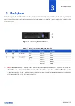
background image


SK32303 Series


Backplane | 

19 

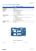
3-1 Storage Backplane Options


SK32303 series supports the below backplanes:


1 x 

3.5” 

3-port 12Gbps SAS/SATA passive backplane 


All available SAS/SATA backplanes include the following common features: 


12Gbps SAS and 6Gbps SAS/SATA 


29-pin SFF-8680 12Gbps rated drive interface connectors, providing both power and I/O signals to attached devices 


Hot-swap support for SAS/SATA devices 


I2C interface from a 4-pin connector for device status communication to the BMC over SMBus 


Summary of Contents for SK32303 Series

Page 1: ...SK32303 Series SK32303 Series Storage Expansion Kit User Manual January 2020 Version 1 1 A document provides an overview of product features functions architecture and support specifications ...

Page 2: ...ge in trade This document contains information on products services and or processes in development All information provided here is subject to change without notice Contact your Chenbro representative to obtain the latest Configuration Guide The products and services described may contain defects or errors known as errata which may cause deviations from published specifications Current characteri...

Page 3: ...l Panel 9 1 4 System Dimensions 10 1 5 System Level Environmental Specifications 11 1 6 System Packaging 12 2 Installation and Removal 13 2 1 Storage Kit Installation 13 2 2 HDD Tray Installation Removal 15 2 3 Storage Kit Fan Module Maintenance 17 3 Backplane 18 3 1 Storage Backplane Options 19 3 2 3 5 12Gbps SAS SATA Backplane 20 4 Maintenance and Service 22 ...

Page 4: ...ion 2 13 Figure 7 Storage kit installation 3 14 Figure 8 3 5 HDD installation screw type 15 Figure 9 3 5 HDD removal screw type 15 Figure 10 2 5 HDD SSD installation screw type 16 Figure 11 2 5 HDD SSD removal screw type 16 Figure 12 Storage kit fan module installation 17 Figure 13 Storage kit fan module removal 17 Figure 14 Drive tray LED identification 18 Figure 15 Backplane front view 20 Figure...

Page 5: ...e 2 Front control panel 9 Table 3 System environmental specifications summary 11 Table 4 System packaging information 12 Table 5 Product weight information 12 Table 6 Drive power LED activity LED behavior 18 Table 7 Backplane specifications 20 Table 8 Connector and pin header function description 21 ...

Page 6: ...ils for each major component feature or option are provided in the following chapters Table 1 Chenbro SK32303 series specifications Feature Description Dimension D x W x H 218 7 x 146 0 x 84 4 mm 8 61 x 5 75 x 3 32 Drive Bay 3 x 3 5 HDD Tray Indicator 1 x Power Status 1 x HDD Status System Security 1 x System Alarm Front Control Alarm Mute Cooling Fan 60 x 25 mm 1 Material SGCC Net Weight 1 4 kg B...

Page 7: ...SK32303 Series Product Overview 7 1 1 Front Panel Figure 1 Front panel A Alarm Mute B 3 5 Storage Drive Bays C Indicator ...

Page 8: ...SK32303 Series Product Overview 8 1 2 Back Panel Figure 2 Back panel A Power Connector B SATA 3 0 Connectors C Fan Connector D Cooling Fan ...

Page 9: ...ries Product Overview 9 1 3 Front Control Panel Figure 3 Front control panel Table 2 Front control panel Label ICON Indicator button or connector A AlarmOffSwitch B TemperatureAlarmLED C FanAlarmLED D HDDAlarmLED ...

Page 10: ...SK32303 Series Product Overview 10 1 4 System Dimensions Figure 4 Chassis dimensions ...

Page 11: ...st performance reliability and data integrity Class 2 A second tier of performance reliability and data integrity HDD I O throughput degradation SPEC Pass Fail Criteria No functional failure during test or post test diagnostics Requirement to pass test is based on IOMeter data throughput in IO s per second expressed as a percent of Test HDD maximum theoretical baseline performance Class1 90 of bas...

Page 12: ...omponent In addition all inner packaging components MUST be reinstalled in the proper location to ensure adequate protection of the system for subsequent shipment Table 4 System packaging information Part Number Single Bulk Form Factor mm Support Level 387 32303 5403A0 Single N A Stand Alone NOTE The design of the inner packaging components does not prevent improper placement within the packaging ...

Page 13: ...nstallation and Removal SK32303 series supports up to 3 x 3 5 hot swap SAS SATA HDD with an additional cooling fan module as a peripheral component 2 1 Storage Kit Installation Figure 5 Storage kit installation 1 Figure 6 Storage kit installation 2 ...

Page 14: ... installation 3 1 Insert the storage kit into the 5 25 3 bay drive cage 2 Align the mounting holes and secure with screws as shown 3 Note If the system chassis comes with tool less installation rails for 5 25 bays secure the storage kit with rails before inserting ...

Page 15: ...ation Removal Figure 8 3 5 HDD installation screw type 1 Align the front of HDD with the anchor point on the tray 2 Secure 3 5 HDD with tray by four screws as shown Figure 9 3 5 HDD removal screw type 1 Loosen four screws as shown 2 Detach the 3 5 HDD from the tray ...

Page 16: ...D installation screw type 1 Align the front of HDD SSD with the anchor point on the tray 2 Secure 2 5 HDD SSD with the tray by four screws from the tray bottom Figure 11 2 5 HDD SSD removal screw type 1 Loosen four screws as shown 2 Detach the HDD SSD from the tray ...

Page 17: ...bottom of the fan module to the rear of the storage kit as shown 2 Align and press the fan module until it is fully attached 3 Plug the fan power connector in the backplane Figure 13 Storage kit fan module removal 1 Unplug the fan power connector 2 Lift the two tabs on the fan quad and release the fan carefully away from the module as shown ...

Page 18: ...ED ICON LED Color Behavior Condition A Power LED N A Stay off Fault Blue Solid on Present B Activity LED Green Solid on Access Red Solid on Failure 1Hz blink Rebuild 4Hz blink Locate NOTE The drive activity LED is driven by signals from the drive itself Drive vendors may choose to operate the activity LED different from what is described in the table above Should the activity LED on a given drive ...

Page 19: ...lane All available SAS SATA backplanes include the following common features 12Gbps SAS and 6Gbps SAS SATA 29 pin SFF 8680 12Gbps rated drive interface connectors providing both power and I O signals to attached devices Hot swap support for SAS SATA devices I2C interface from a 4 pin connector for device status communication to the BMC over SMBus ...

Page 20: ...Off Fault Blue on Present Activity LED Green on Access Red on Failure Environment Monitor Temperature senor TMP75 detection U2 Connector 1 3 x SATA 7 pin 2 3 x SFF 8680 3 1 x Standard 4P power connector for 5V 12V from power supply 4 1 x pin header 2 54 mm 2 x 5 5 1 x pin header 2 0 mm 2 x 8 6 1 x pin header 2 0 mm 1 x 3 7 1 x I2C Connector wafer 2 54 mm 1 x 4 Dimension L x W x H 142 0 x 80 7 x 2 ...

Page 21: ...this configuration is highly recommended C Fan There is one 4 pin header for the PWM fan and it is alternative solution that the chassis fan can be powered and monitored by this backplane instead of a motherboard If the chassis fan is connected to a mainboard users need to disable the fan monitoring function of backplane by DIP switch SW1 D Signal Indicator The event LED with red black wire is loc...

Page 22: ...ight to examine the DOA products If the damage of DOA products is caused by improper action as described above the customer will be liable for paying the related charge having occurred or paying the fee of the replacements if the DOA products are totally scrapped TECHNICAL SUPPORT Please provide following information when you apply our technical support Product model name and or part number Produc...

Reviews: