background image

SR209 Plus Series


13 

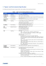
1-7 System Level Environmental Specifications


The following table defines the system level specification under operating and non-operating environment. 


Table 3


    System environmental specifications summary


Parameter


Specification


Temperature 

Operating 

5º C to 35º C (41º F to 95º F) 

Temperature 

Non-Operating 

-40º C to 70º C (-40º F to 158º F) 

Humidity 

Non-Operating 

50% to 90%, non-condensing with a maximum wet bulb of 28° C (at temperatures 
from 25° C to 35° C) 

Unpackaged 
Shock 

Non-Operating 

Trapezoidal, 25 g, velocity change is based on product weight 

Vibration 

Operating 

5 Hz @ 0.0002 g2/Hz to 350 Hz @ 0.0002 g2/Hz 
Input acceleration is 0.26 g RMS 
10 minutes per axis for all 3 axes on all samples 
Random control limit tolerance is ± 3 dB 

Sag & Bow 

Non-Operating 

Tolerance analysis among rack, rail and chassis 
Actual on rack test with EIA Go-NoGo fixture 

EMI 
Pre-scan 

Radiated Emissions 

CISPR CLASS A (under 6dB): 
30~1000 MHz vertical/horizontal 
1G~6G GHz vertical/ horizontal 
1G~18G GHz vertical/horizontal 

RVI 

Operating 

HDD class 


Class 1: Highest performance, reliability, and data integrity 


Class 2: A second tier of performance, reliability, and data integrity 

HDD I/O throughput degradation SPEC 
Pass/Fail Criteria 


No functional failure during test or post-test diagnostics. 


Requirement to pass test is based on IOMeter data throughput (in IO’s per 

second) expressed as a percent of Test HDD maximum theoretical baseline 
performance 


Class1: > 90% of baseline for 4K random writes and > 80% of baseline for 
128K sequential writes.   


Class2: > 85% of baseline for 4K random writes and > 75% of baseline for 
128K sequential writes. 


Mix: > 80% of baseline for 4K random writes and > 70% of baseline for 
128K sequential writes. 

Packaged 
Vibration 

Non-Operating 

ISTA (weight over 68 kg, 1B; weight equal or less than 68 kg, 1A) 

Packaged Drop 

Non-Operating 

Drop height change is based on product weight 
Non-palletized product: 


Investigation: Test requirement is 6 face drops, 8 corner drops and 12 edge 
drops for a total of 26 drops. 


Validation: Test requirement is 6 face drops, 2 corner drops and 3 edge 
drops for a total of 11 drops. 

Palletized product: (Both investigation and validation) 


Perform two bottom drops at the specified height, 10 bottom drops at one 
half of the specified height. 


Perform 4 rotational edge drops (one per edge) at the specified height. 


Summary of Contents for SR209 Plus Series

Page 1: ...SR209 Plus Series Server Chassis User Manual November 2019 Version 2 1 A document provides an overview of product features functions architecture and support specifications...

Page 2: ...age in trade This document contains information on products services and or processes in development All information provided here is subject to change without notice Contact your Chenbro representati...

Page 3: ...ns 13 1 8 System Packaging 14 2 System Components Installation and Removal 15 2 1 Side Cover Installation 15 2 2 Front Bezel Installation 16 2 3 5 25 Device Installation 17 2 4 HDD Cage Installation 1...

Page 4: ...on 19 Figure 17 3 5 hot swap HDD cage installation 19 Figure 18 3 5 hot swap HDD cage fan maintenance step 1 20 Figure 19 3 5 hot swap HDD cage fan maintenance step 2 20 Figure 20 3 5 hot swap HDD car...

Page 5: ...specifications summary 13 Table 4 System packing information 14 Table 5 Product weight information 14 Table 6 Drive power LED activity LED behavior 27 Table 7 Backplane specifications 29 Table 8 Conn...

Page 6: ...ap Option 4 x 3 5 Internal Option Storage Backplane 1 x 3 5 4 port 12Gbps Mini SAS HD Passive Backplane 1 x 3 5 4 port 12Gbps SAS SATA Passive Backplane PSU Form Factor PS 2 Single or N 1 Redundant In...

Page 7: ...eries 7 1 1 Front Panel Figure 1 Front panel enclosed A 5 25 Storage Drive Bay B Front Control Panel C USB Port Blank Figure 2 Front panel open A Bezel Door B 3 5 Storage Drive Bay C Front Control Pan...

Page 8: ...SR209 Plus Series 8 1 2 Back Panel Figure 3 Back panel with redundant PSU A 1 1 Redundant PSU B Rear I O C Rear Fan D Expansion Slot Opening...

Page 9: ...SR209 Plus Series 9 1 3 Security Features Figure 4 Key lock and Kensington slot location Figure 5 Intrusion switch location A Key Lock B Side Cover Lock C Kensington Slot D Intrusion Switch...

Page 10: ...igure 6 Front control panel Figure 7 Front control panel Table 2 Front control panel Label ICON Indicator button or connector A PowerButton B LAN1 LAN2ActivityLED C PowerLED D HDDActivityLED E FanAlar...

Page 11: ...SR209 Plus Series 11 1 5 Chassis Dimensions Figure 8 Chassis dimensions...

Page 12: ...SR209 Plus Series 12 1 6 Interior View Figure 9 Chassis components A 3 5 HDD Cage Slot B Power Supply Unit C 5 25 Storage Drive Bay D PCIe Fan Option E System Board...

Page 13: ...reliability and data integrity Class 2 A second tier of performance reliability and data integrity HDD I O throughput degradation SPEC Pass Fail Criteria No functional failure during test or post test...

Page 14: ...quent shipment Table 4 System packing information Part Number Single Bulk Form Factor mm Support Level 387 20969 2100A0 Single 350 x 734 x 820 L5 NOTE The design of the inner packaging components does...

Page 15: ...S SATA HDD Support for different storage and peripheral options will vary depending on the system model and or available accessory options installed 2 1 Side Cover Installation Figure 10 Side cover in...

Page 16: ...right side of the bezel on the front chassis 2 Fully attach the bezel on the front of the chassis and make sure the internal latches x 2 are up 3 Push down the bezel until it is secured Figure 12 Beze...

Page 17: ...removal 1 Press two sides of the latch of the blank to release the blank as shown 2 Pull the blank out Figure 14 5 25 device side rail installation 1 Take the reserved side rails located inside the d...

Page 18: ...SR209 Plus Series 18 Figure 15 5 25 device installation 1 Insert the 5 25 device into the drive bay Note Make sure both side rails are clipped on the latch...

Page 19: ...the reserved slot 2 Insert the HDD cage into the chassis 3 Secure the thumb screws on the four sides of the HDD cage 4 Plug the fan power connector into the system board Figure 17 3 5 hot swap HDD cag...

Page 20: ...g the power connector from the backplane 2 Release the fan latch and pull the fan out of the fan cage 3 Remove the tool less fan holder as shown and replace with a new fan 4 Insert the fan into the fa...

Page 21: ...er removal 1 Press the carrier button to release the carrier 2 Pull the lever to remove the carrier from the HDD cage Figure 21 3 5 hot swap HDD carrier installation 1 Insert the HDD carrier into the...

Page 22: ...mples lock into place NOTE Due to degraded performance and reliability concerns the use of the 3 5 drive blank filler as a 2 5 device bracket is intended to support SSD type storage devices only Insta...

Page 23: ...SR209 Plus Series 23 Figure 24 2 5 SSD installation screw type 1 Align front HDD with the anchor point on the carrier 2 Assemble 2 5 SSD into the carrier by three screws from the bottom as shown...

Page 24: ...as shown 2 Insert the fan module into the reserved fan slot as shown NOTE Please notice the arrow on the fan holder pointing the rear 3 Plug the power connector into the system board Figure 26 Optiona...

Page 25: ...1 Lift up the fan latch at the bottom of the fan module without release 2 Push the fan module down to remove it from the chassis 3 Remove the fan from the tool less fan holder as shown and replace the...

Page 26: ...2 7 Power Supply Installation Figure 29 Single PSU installation 1 Place the PSU inside the chassis and ensure the alignment for four screw holes of PSU and bracket of the chassis matched 2 Secure the...

Page 27: ...D ICON LED Color Behavior Condition A C Power LED N A Stay off Fault Blue Solid on Present B D Activity LED Green Solid on Access Red Solid on Failure 1Hz blink Rebuild 4Hz blink Locate NOTE The drive...

Page 28: ...patible backplanes include the following common features 12Gbps SAS and 6Gbps SAS SATA 29 pin SFF 8680 12Gbps rated drive interface connectors providing both power and I O signals to attached devices...

Page 29: ...Blue Present Access LED Green Busy Error LED Red Error Environment Monitor Temperature sensor TMP75 Connector 1 1 x Mini SAS HD 2 4 x SFF 8680 SAS 3 2 x 4 pin peripheral power connector for 5V 12V fro...

Page 30: ...are supplied with stable power inputs If the chassis fan is also powered by fan header JF01 this configuration is highly recommended C Fan There are two 4 pin headers for the PWM fan and it is altern...

Page 31: ...nd configured through this DIP switch It can manage the functions of PWM fan temperature threshold I I2C The motherboard can monitor HDD temperature and fan status through this connector However the I...

Page 32: ...indicates storage device status Power LED Blue Present Access LED Green Busy Error LED Red Error Environment Monitor Temperature sensor TMP75 Connector 1 4 x SATA 2 4 x SAS29 3 4 x Big 4P Power connec...

Page 33: ...SR209 Plus Series 33 Figure 34 Backplane front view A HDD_00 C HDD_02 B HDD_01 D HDD_03 Figure 35 Backplane rear view...

Page 34: ...s fan can be powered and monitored by this backplane instead of motherboard If the chassis fan is connected to mainboard user needs to disable the fan monitoring function of backplane by DIP switch SW...

Page 35: ...amine the DOA products If the damage of DOA products is caused by improper action as described above the customer will be liable for paying the related charge having occurred or paying the fee of the...

Reviews: