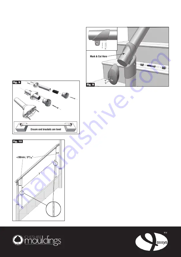
into the newel connector using the 45mm
bolt and spacer provided, making sure the
chamfered end goes into the hole first. Finish
off by inserting the cover cap (fig. 8).
With the handrail connector secure, cut the
handrail at a 90
o
angle in line with the newel
post, leaving 20mm protruding at the bottom
of the handrail (
this can be altered to achieve a
larger or smaller gap, 20mm will leave a 10mm
gap
). You can now fit the end cap securing
with two 30mm screws provided. (fig. 8).
Baluster Assembly
Please Note;
When assembling the baluster brackets onto a baluster
tube, remember to slide the baluster bracket covers onto
the tube first followed by the tube bung and finally the
baluster bracket, then lie each baluster bracket onto a
separate piece of wood to ensure that they are both level/
square with each other. Now tighten the fixing screws
prior to sliding the baluster bracket cover over the baluster
bracket, the baluster assembly is now ready to be fixed
on the hand/base rails (fig. 9).
All holes for fixing the baluster brackets should be pre-drilled. The
bottom baluster should be fixed vertically no more than 99mm from
the narrowest part of the newel post, in the same way as the top
baluster was previously (fig. 10).
In order to space the remainder of the balusters evenly measure
the distance in mm between the centre points of the 2 balusters
already fitted and divide by 148.5. Round the answer up to the next
whole number and divide the whole number back into the original
measurement and this will give you the exact spacing (fig. 10).
Example - 2264mm between centre points of balusters divided
by 148.5mm = 15.25, rounded up to 16, then take the Evolutional
measurement 2264mm divided by 16 = 141.5mm which is the
exact spacing measurement.
Pre-drill all holes for the baluster brackets after marking their position
on the hand rail and base rail, using the spacing measurement
from the previous step.
axxys
®
evolution
fitting instructions


