1.0 05/05/2013
23
During the period of the engagement of the change gears, first cut off the power. Turn the
switch of the machine tool to the "Off" position and then loosen the two hexagon socket head
cap screws on the gear housing to dismount the housing.
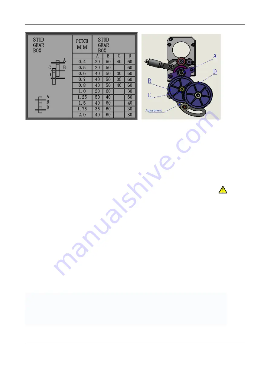
The simple gear rotation structure is illustrated on the left and the intermediate idler gear
is illustrated on the right in the figure above and, as long as the size of the gears can meet the
connection between A and D, it will be all right.
(1) Loosen the hexagon socket head screws to ensure that the change gears A and D
should be connected to change gears B and C.
(2) Disengage the gears B and C completely, loosen the nut on the fixed axle and
re-adjust as required to ensure them engaged with gear A.
(3) When replacing the change gears required for change of the thread pitch for thread
cutting, attention should be on the small keys on each axis and the gear marking engraved on
each gear and do not engage them in a wrong way.
Notice: For the system of a set of gears, the gear D has a pad with a key on the screw shaft
used for positioning, which is designed to ensure that the gear D and the gear C engaged and
connected shall be in alignment and maintained in a straight line.
(4) Go on to regulate gears B, C and A, then rotate the spindle by hand, try to rotate back
and forth and observe and, when the situation is normal, tighten up the nut of the axis on the
change gear frame.
When recovering the gear housing, ensure that the two cylinder head bolts are tightened
up.
Turning Thread
Turning the screw threads is, in fact, to rely on the shape of the tool for cutting, the product
operation instructions will not contain any relevant provisions of the cutting tool types, the
scopes, the cutting speeds and suitable materials. For specific details, consult the experienced
professionals or refer to the professional manuals for details.


