1.0 05/05/2013
38
Step Two
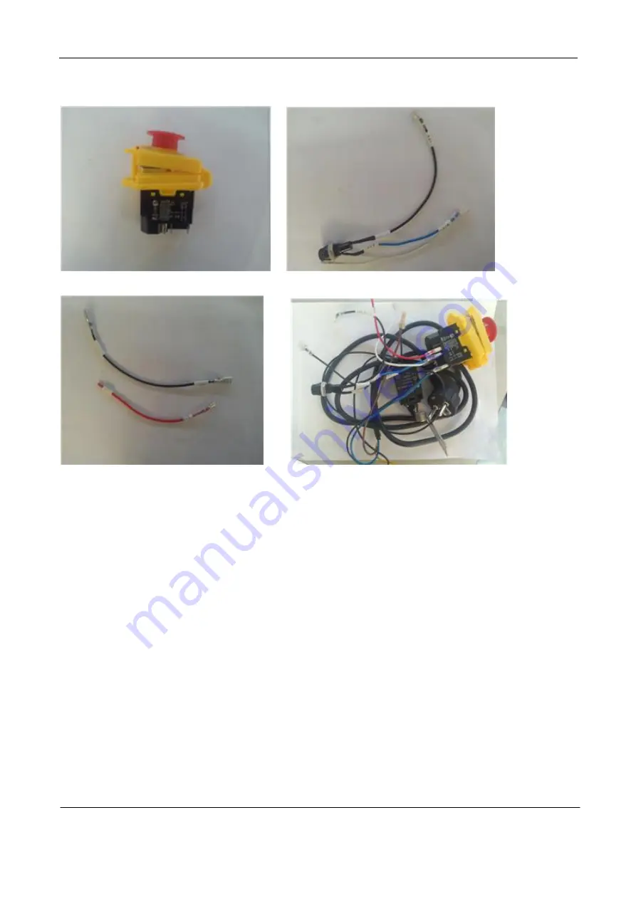
Fig.1 Fig.2
Fig.3 Fig.4
1.
There are the start and the stop buttons in the button switch, the terminals 13 and 23 are
connected to the incoming power and the terminal 14 and 24 are connected to the controller
(as shown in Fig.1).
2.
Connection method of two terminals of fuse (as shown in Fig.2).
3.
The purple wire of the plug wires and the line introduced from QKS7 are connected with the
terminal 13 and 23 of the button switch respectively, the two wires of the fuse are combined
together into a terminal and then connected with the terminal 14 (or 24) of the button switch
and the terminal 24 (or 14) of the button switch is connected with the black wire (as shown in
Fig.3) and the wire A1 of the button switch is connected with the red wire (as shown in Fig.3),
(as shown in Fig.4).
4.With the step completed, there are now four terminals.


