Compound Rest
Follow the same procedure as the cross-slide adjustment to adjust the compound
rest, the rear gib screw is shown (A, Fig 22), the front gib strip (Not shown) is by the
handwheel.
Tailstock
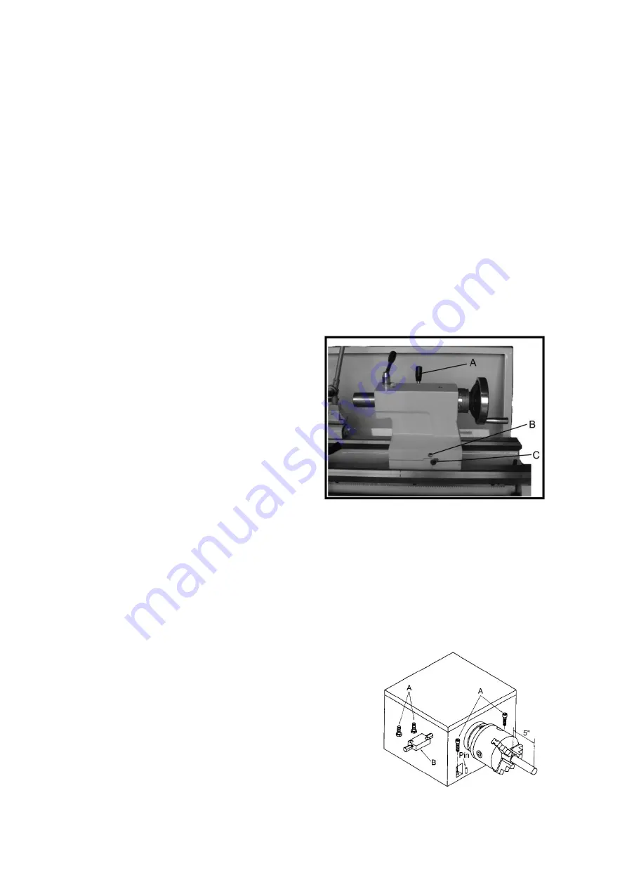
If the handle will not lock the tailstock, follow the procedure below:
1.
Lower the handle to the
unlocked position.
2.
Slide the tailstock to an
area that allows access to the underside of the tailstock.
3.
Tighten the tailstock
clamping bolt (underside of the tailstock) ¼ turn. Test the lock to make sure it
locks the tailstock properly and repeat as necessary.
Tailstock Off-Set
Follow the procedure below to off-set the
tailstock to cut shallow tapers:
1.
Lock the tailstock into position by
raising the handle (A, Fig 23)
2.
Alternately loosen and tighten two hex
socket cap screw (B, Fig 23).
Tailstock Gibs
Take up any play in the tailstock by tightening the two gib sscrews (C, Fig 23) on
either side of the tailstock base.
Note:
Do not over tighten, excessive tightening will lead to premature wear of the
gibs and mating parts.
Headstock Alignment
The headstock has been aligned at the factory and should not require adjustment,
however, if adjustment is deemed necessary, follow the procedure below to align the
headstock:
1.
Using a machinist’s precision level on the
bedways, make sure that the lathe is level side
to side and front to back. If the lathe is not
level, correct to a level condition before
proceeding. Re test the alignment if any
adjustments were made.
21
Summary of Contents for Voyager Lathe
Page 19: ...Inch Lead and Feed Table Compound Rest 19...
Page 25: ...Parts List and Diagrams Headstock Assembly I 25...
Page 26: ...No Part No Description Size Qty 26...
Page 29: ...Headstock Assembly II 29...
Page 32: ...Headstock Assembly III 32...
Page 35: ...Gearbox Assembly I 35...
Page 38: ...Gearbox Assembly II 38...
Page 41: ...Apron Assembly I 41...
Page 43: ...Apron Assembly II 43...
Page 45: ...Saddle and Cross Slide Assembly 45...
Page 48: ...Top Slide and Tool Post 48...
Page 50: ...Tailstock Assembly 50...
Page 52: ...Bed and Shaft Assembly 52...
Page 55: ...Stand and Brake Assembly 55...
Page 57: ...48 GH1440A 01723 Cover 1 49 GH1440K 22701A Brake Pedal 1 50 GH1440K 22717 Stand Front 1 57...
Page 58: ...End Gear Assembly 58...
Page 62: ...Steady Rest 62...
Page 64: ...Electrical Components 64...


