6
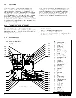
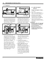
1 If practical, place the dial indicator tip
on the end of the shaft sleeve or on a
step in the shaft to measure end play.
Alternately push and pull the shaft in
the axial direction. If the bearings are
in good condition, end play should
not exceed 0,13 mm (.005").
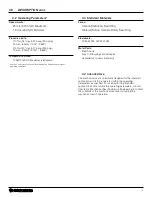
3 Remove all sharp corners, burrs, and
scratches on the shaft, especially in
areas where the O-Ring will slide, and
polish if necessary to achieve a 0,8
micron (32 microinch) Ra finish. Make
sure the shaft or sleeve diameter is
within 0,05 mm (.002") of nominal.
4 Use a dial indicator to measure the
shaft runout in the area where the
seal will be installed. Runout should
not exceed 0,001 mm TIR per
millimeter (.001 inch TIR per inch) of
shaft diameter.
5 Protect the shaft O-Ring by
lubricating the shaft with a clean
silicone based lubricant, such as that
provided with the seal.
6
Check availability of clean dry
barrier gas.
The seal uses gas
(Nitrogen) to seal the product from
the environment and lubricate the seal
faces. 2,4 lpm (5 SCFH) of barrier
gas must be available at 2 bar (30
psi) over the maximum stuffing box
pressure and filtered to a maximum
particle size of 3 microns with a dew
point of <-29°C (-20°F). Alternate gas
can be used for barrier gas supply if
it is compatible with the product and
the environment.
4.0 PREPARATION FOR INSTALLATION
4.1 Equipment
.005"
0,13 mm
<
ø
1000
ø
<
32 µ"
0,8 µm
R
a
ø
<
.002"
0,05 mm
±
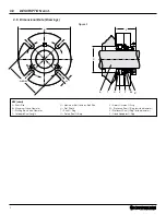
2 If possible, attach a base dial
indicator to the shaft and rotate both
the indicator and shaft slowly while
reading the runout of the stuffing box
face. Misalignment of the stuffing box
face relative to the shaft should not
exceed 0,005 mm TIR per mm (.005
in per inch) of shaft diameter.
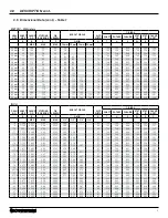
The stuffing box face must be flat
and smooth enough to seal the
gland. Surface roughness should
be 3,2 microns (125 microinch) Ra
maximum for gaskets and 0,8 micron
(32 microinch) Ra for O-Rings. Steps
between halves of split case pumps
should be machined flat. Make sure
the stuffing box is clean and clear
along its entire length.
ø
ø
200
<
125 µ"
3,2 µm
4.2 4400H TwinHybrid
™
Gas Seal
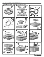
1 Review seal packaging ensuring no
damage or shortage has occurred to
the contents.
2 Review the seal fit dimensions in
Table 1 to ensure the equipment to be
sealed has the required dimensions.
3 Record the seal Item Number
and Name found on the label for
referencing when contacting AW
Chesterton Application Engineering.
4 Check the chemical listing to
determine if the O-Rings installed in
this seal are compatible with the fluids
being sealed.
IMPORTANT:
5
Check the rotation of the pump and
the rotation arrow on the gland OD
(and/or gland face) ensuring both
are the same direction.
6
Make sure all set screws are
engaged in the sleeve but do not
protrude into the inside diameter
of the seal sleeve.


