7
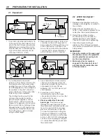
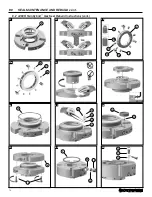
1 Slide the seal onto the shaft.
2 Reassemble the pump and make
necessary shaft alignments and
impeller adjustments. The impeller
can be reset at any time, as long as
the centering clips are in place and
the seal set screws are loosened
while the shaft is being moved.
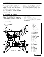
3 The 1/4 dog point set screws (marked
1, 2, 3) go into the small holes in the
sleeve.
Do not disengage these
screws from the sleeve when
positioning the seal.
4 The centering clips have been preset
at the factory. If for any reason you
loosen or remove the centering clip
cap screws, re-tighten each cap
screw finger tight (approximately 1,7
N-m [15 inch-pounds] of torque).
CAUTION
:
Make sure the lip on the end of the
gland is inside the inner centering clip
groove and the lock ring lip engages
the outer centering clip groove.
5 Orient the gas barrier supply and flush
connections to the location required.
TABLE 2 – Gland Port Functions
“B”
Barrier Gas Supply
“F”
Flush - Environmental
“M”*
Monitor Port
“X”
Manufacturing Port (Do Not Use)
*Previously identified as “BG”
CAUTION:
All ports are plugged prior to
shipping. These plugs prevent dirt and
contaminants from entering the seal.
When plugs are removed ensure that
dirt, liquid and contamination, which
could cause seal malfunction, do not
enter the seal ports.
6 Tighten the stuffing box bolts evenly
to the recommended torque value in
TABLE 3.
**Stuffing box bolts vary per
application. Actual torque required
is based on bolt size and bolt
manufacturers’ recommended torque.
5.0 SEAL INSTALLATION
TABLE 3 – Recommended Torque Values
Seal Size
Dog Point &
Cup Point Set Screws
Gland Screws
Stuffing Box Bolts**
up to 65 mm
(up to 2.625")
5,7 - 6,8 N-m
(50 - 60 in-lbf)
12,2 N-m
(9 ft-lbf)
27 - 40 N-m
(20 - 30 ft-lbf)
>65 mm up to 90 mm
(>2.625" up to 3.625")
7,3 - 8,3 N-m
(65 - 75 in-lbf)
12,2 N-m
(9 ft-lbf)
34 - 48 N-m
(25 - 35 ft-lbf)
IMPORTANT:
The stuffing box bolts must be
tightened before tightening the set
screws onto the shaft or seal port
connections.
7 Tighten 1/4 dog point set screws
(marked 1, 2, 3) in two steps:
Step 1 – snug to finger tight; Step
2 - retighten 1/4 dog point set screws
evenly with the hex key provided and
to the recommended torque value in
TABLE 3.
IMPORTANT:
All three 1/4 dog point set screws must
be tightened FIRST.
8 Evenly tighten the cup point set
screws (marked 4, 5, 6) to the shaft
using recommended torque value in
TABLE 3. If rotation of the lock ring
is required for tightening set screw,
loosen but do not remove centering
clips.
IMPORTANT:
The cup point set screws installed in
the lock ring are hardened steel and
have metric threads: for 25 mm – 65
mm (1.000" thru 2.625") seals use a
3 mm hex key; for 70 mm – 90 mm
(2.750" thru 3.625") seal use a 4 mm
hex key. Stainless steel cup point
set screws are provided in the seal
accessory kit, which may be used for
low pressure, non-hardened shaft/
shaft sleeve applications.
9 Remove socket head cap screws and
centering clips from the lock ring and
retain for later use.
10 Ensure that the gland is properly
centered over the sleeve. To do
this, turn the shaft toward the
directional arrow by hand to ensure
the seal turns freely. I metal to metal
contact is detected within the seal
it is improperly centered. Replace
centering clips finger tight, loosen
gland bolts, tighten clips, re-tighten
gland bolts and remove clips. If metal
to metal contact is still detected,
check concentricity of the shaft to the
stuffing box.
THE BARRIER GAS SUPPLY AND
FLUSH CONNECTIONS ARE 1/4" NPT.
11 If a flush/recirculation port is
required, remove the shipping plug
and connect the pump discharge/
suction to the flush port marked “F”
using a recirculation line (bleed from
discharge [API Plan 11] or connected
to suction [API Plan 13]). This is
recommended in seal applications
where the barrier gas supply may
be disrupted during operation. This
connection may also be used to
monitor stuffing box pressure by
installing a connection to a gauge or
pressure transducer.
12 Connect the barrier gas supply
port marked “B”. Purge the barrier
gas supply line from the barrier
gas supply manifold or system.
Prior to connecting to the seal port
ensure the supply line is free of
contamination, dirt and liquid and
no burrs, restrictions or liquid legs
are present. Full pressure barrier gas
supply can be piped directly to the
barrier supply port.
The seal In-Gland Control System
(IGCS) will maintain a factory preset
differential pressure between the
barrier gas at the seal interface and
the product pressure in the stuffing
box.
13 All ports must either be connected
to piping or have a metal pipe
plug installed. Use Chesterton
recommended PTFE tape to install
piping or plugs.
It is recommended to monitor barrier
gas pressure. Use the gauge port
connection marked “M”* (located
opposite the barrier gas supply port).
IMPORTANT:
All plastic shipping plugs must be
replaced.
CAUTION:
Operation without sufficient barrier
gas supply can cause a loss in seal
performance or failure. The barrier
gas supply must be on whenever
the pump is pressurized or contains
liquid product. The seal will regulate
the usage of barrier gas; do not limit
the flow by use of flow restrictors or
valves.


