background image

ARION : 600 SERIES

  - 


Safety Information

This assembly guide applies to the following ARION Enclosure: 600 Series

PREFACE:


This assembly guide is provided to prevent service personnel from committing an act that results in the risk of fire, electric shock, or injury to persons. The equipment shall be 

installed or serviced by trained service personnel in accordance with the applicable requirements of the National Electrical Code, NFPA 70-1999 or Canadian Electrical Code and 

the applicable sections of ANSI C2, the National Electrical Safety Code. Not following these instructions could result in the risk of fire, electric shock, or injury to persons.

SAFETY SYMBOLS USED IN THIS MANUAL

This assembly guide provides general safety guidelines to be observed during installation, operation, and maintenance of the ARION Enclosure.

SAFETY CONSIDERATIONS

•  When applicable, rack systems are not intended as enclosures and do not provide any degree or protection as that of an enclosure.
•  Only UL     Listed ITE (Information Technology Equipment) units should be installed inside the ARION Enclosure.
•  Be sure to read and follow all individual manufacturer equipment manuals for safety and installation instructions.
•  Proper spacing is required when installing electrical equipment to avoid electrical shock. Maintain minimum spacing between the accessories and components and the 

computer enclosure assembly for safe operation of the equipment when installed in accordance with the specification.

R

WARNING: 

Improper handling and use of the ARION Enclosure could result in equipment damage, serious injury, or possible death.

WARNING:


•  Only indentical ARION enclosures should be installed together when ganging. 
•  The ambient temperature operating range for the ARION Enclosure and accessories is +50 to +95˚F (+10 to +35˚C).
•  The non-operating temperature is -4 to +140˚F (-20 to +60˚C).

•  Once in place at the desired/intended location, deploy the leveling feet for maximum stability.
•  If stabilizing brackets are used, they must be tightened until they are flush to the frame.
•  Rated or maximum load capacity for the ARION Enclosure is 1,400 kilograms on the floor or on leveling glides.
•  No EIA slide rail location instructions are provided here, location is determined by end user.
•  To maintain a uniform distribution of the mechanical load in the ARION Enclosure, load the heaviest equipment first, at the bottom of the ARION  Enclosure and load the 

lighter unit at the top.

WARNING: 

Only install equipment after the ARION Enclosure has been property secured. If you need to move the enclosure after equipment installation, exercise extreme 

caution to avoid the enclosure tipping over.  The casters are rated to about 650 lbs each dynamic load.  Moving a fully loaded cabinet will generate heat which can damage

the casters.  To avoid overheating, move the enclosure a maximum of 100 yards, then stop for 2 minutes and allow the casters to cool down.  Repeat until final location 

is reached.

WARNING: 

Be careful when moving enclosures before installation. Sudden stops and starts, excessive force, obstructed routes, and uneven floor surfaces may cause the 

enclosure to topple over.

LOADING EQUIPMENT:

WARNING :


Failure to follow directions in the warning could result in injury to persons or loss of life.

TIP :


Indicates a recommended way of working.

Summary of Contents for ARION 600W Series

Page 1: ...International Version AAG 20 03 002...

Page 2: ......

Page 3: ...esult in equipment damage serious injury or possible death WARNING Only indentical ARION enclosures should be installed together when ganging The ambient temperature operating range for the ARION Encl...

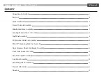
Page 4: ...ly Top Panel Assembly PDU Vertical Cable Rail Assembly PMA 19 Mounting Rails Set Assembly Door Hinges Door Latch Bracket Assembly Front Door Curve Assembly Rear Door Split Assembly Side Panel Assembly...

Page 5: ...ry The recommended equipment for moving the carton are pallet jack or forklift 1 Move the carton to a solid level area clear of obstructions 2 Carefully cut the wrapping straps securing the carton 3 R...

Page 6: ...Assembly Guide Front Door Curve P14 Rear Door split kit P16 ARION 600 SERIES Unpacking Instructions...

Page 7: ...A B C D A B C D Tools Assembly Bag Hardware Bag P18 PMA P10 x 2 P11 x 2 Vertical Post P2 x 4 Top Panel P6 Caster kit P7 x 4 Side Brace Mid P4 x 2 PDU Vertical Cable Rail P8 x 2 Frame Top P3 Frame Bott...

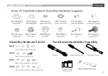
Page 8: ...racket Top Panel Assy Caster kit PDU Vertical Cable Rail Assy PMA Mounting Bracket 1 4 1 2 2 1 4 2 12 P10 P11 P12 P13 P14 P15 P16 P17 P18 PMA Assy LH PMA Assy RH Door Hinges Door Latch Bracket Front D...

Page 9: ...Tools Recommended for Assembly Assembly Hardware Set List ARION 600 SERIES Tools Hardware...

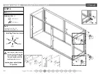
Page 10: ...ssembly Tools Hexagon Socket No 24 16mm Screwdriver Torx T30 Installing Direction Locate Step 1 Step 2 Step 2 Step 1 P2 Cross Section STEP 1 Parts P1 x 1 P2 x 4 P3 x 1 Hardware Set A H1 8 pcs H2 8 pcs...

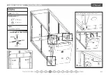
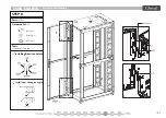
Page 11: ...ARION 600 SERIES Middle Side Brace Assembly STEP 2 Parts P4 x 2 Hardware Set B H6 12 pcs Tools Screwdriver Torx T30 Installing Direction Locate Tighten all location securely...

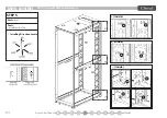
Page 12: ...Leveling Feet And Caster Assembly STEP 3 Parts P7 x 4 Hardware Set B H7 16 pcs H12 4 pcs Tools Hexgon Socket No 10 Open End Wrench No 14 Installing Direction Locate Once in place at the desired locati...

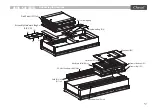
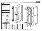
Page 13: ...10 Make sure the Top Panel is installed correctly before tightening Top panel fixing P5 ARION 600 SERIES Top Panel Assembly i i3Inside i i1 i2 STEP 4 Parts P5 x 2 P6 x 1 Hardware Set C H5 2 pcs H7 2 p...

Page 14: ...Inside Inside Inside ARION 600 SERIES PDU Vertical Cable Rail Assembly STEP 5 Parts P8 x 2 Tools Screwdriver Torx T30 Installing Direction Locate...

Page 15: ...MA 19 Mounting Rails Set Assembly P10 N Depth indicator STEP 6 Parts P9 x12 P10 x 2 P11 x 2 Hardware Set C H8 12 pcs H4 12 pcs Tools Hexagon Socket No 13 Picture 1 Picture 2 Use depth indicator label...

Page 16: ...S Door Hinges Door Latch Bracket Assembly STEP 7 Parts P12 x 6 P13 x 1 P15 x 2 Hardware Set D H5 6 pcs H6 6 pcs Tools Screwdriver Torx T30 Picture 1 Picture 2 Check Installing Direction carefully for...

Page 17: ...S T S T ARION 600 SERIES Front Door Assembly STEP 8 Parts P14 x 1 Hardware Set D H5 1 pcs H10 2 pcs H3 1 pcs Tools Screwdriver Torx T30 Install from 90 degree angle Installing Direction Locate...

Page 18: ...U U V V ARION 600 SERIES Rear Door Assembly STEP 9 Parts P16 x 2 Hardware Set D H5 2 pcs H10 4 pcs Tools Screwdriver Torx T30 Install from 90 degree angle Installing Direction Locate H3 2 pcs...

Page 19: ...ARION 600 SERIES Side Panel Assembly STEP 10 1 Parts P17 x 2 Installation Step 1 2 3 Ensure lock is engaged to prevent side panel falling off Installing Direction Locate...

Page 20: ...ARION 600 SERIES Side Panel Assembly STEP 10 2 Parts P17 x 2 Installation Step 1 2 3 Ensure lock is engaged to prevent side panel falling off Installing Direction Locate...

Page 21: ...me Tighten with provided screw Connection of the 19 enclosure to your building s Common Bonding Network CBN is recommended Consult a qualified technician to ensure compliance Pg 17 Your Arion enclosur...

Page 22: ...Pg 18 Overall Dimensions of Assembled Arion Enclosure ARION 600 SERIES Product Information...

Page 23: ...binets including network racks colo racks seismic racks OCP racks and wide range of accessories LIMITEDWARRANTYTERMS AND CONDITIONS Limited Warranty Cheval warrants the Arion series 19 enclosures to b...

Page 24: ......

Reviews: