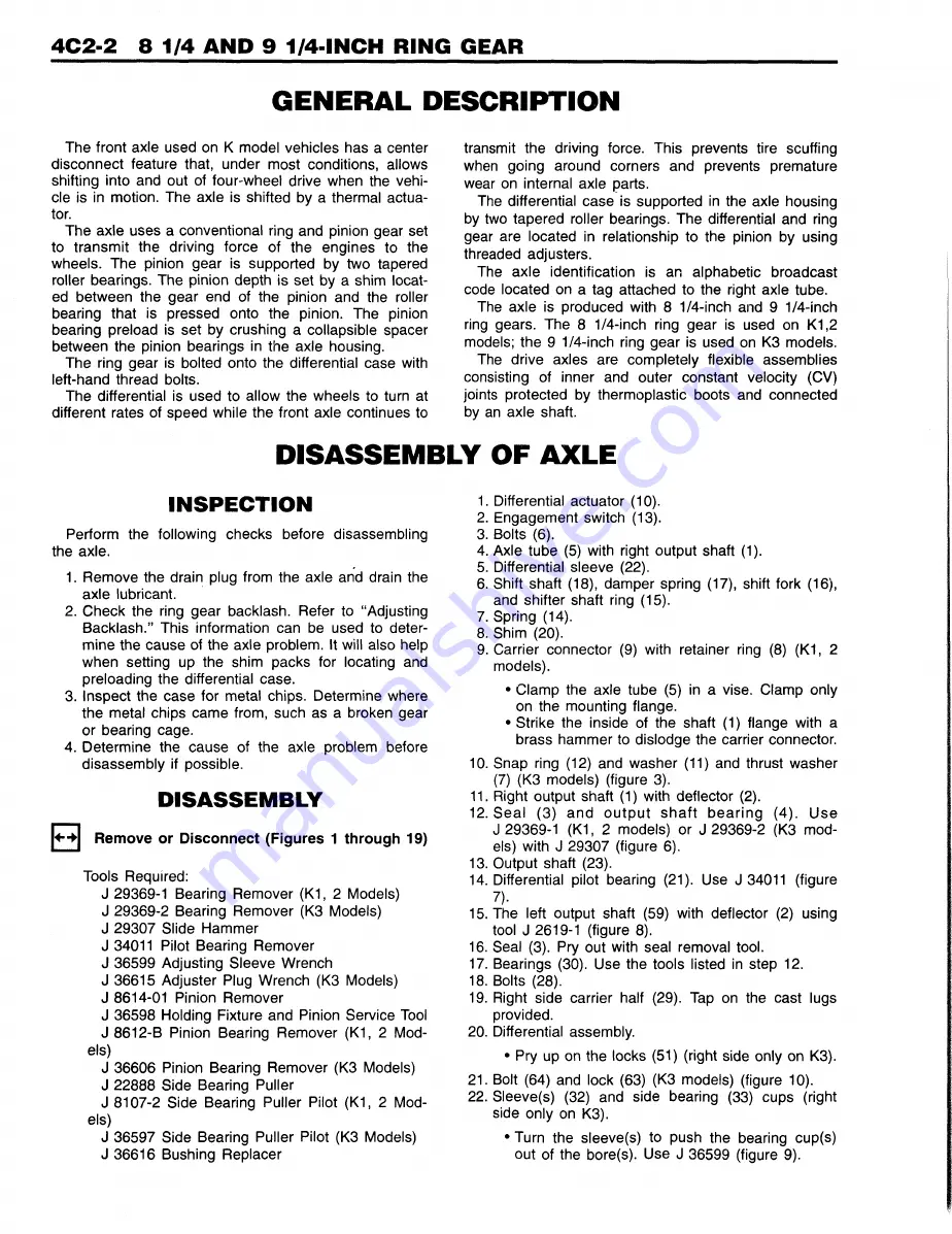
GENERAL DESCRIPTION
The front axle used on K model vehicles has a center
disconnect feature that, under most conditions, allows
shifting into and out of four-wheel drive when the vehi
cle is in motion. The axle is shifted by a thermal actua
tor.
The axle uses a conventional ring and pinion gear set
to transmit the driving force of the engines to the
wheels. The pinion gear is supported by two tapered
roller bearings. The pinion depth is set by a shim locat
ed between the gear end of the pinion and the roller
bearing that is pressed onto the pinion. The pinion
bearing preload is set by crushing a collapsible spacer
between the pinion bearings in the axle housing.
The ring gear is bolted onto the differential case with
left-hand thread bolts.
The differential is used to allow the wheels to turn at
different rates of speed while the front axle continues to
transmit the driving force. This prevents tire scuffing
when going around corners and prevents premature
wear on internal axle parts.
The differential case is supported in the axle housing
by two tapered roller bearings. The differential and ring
gear are located in relationship to the pinion by using
threaded adjusters.
The axle identification is an alphabetic broadcast
code located on a tag attached to the right axle tube.
The axle is produced with 8 1/4-inch and 9 1/4-inch
ring gears. The 8 1/4-inch ring gear is used on K1,2
models; the 9 1/4-inch ring gear is used on K3 models.
The drive axles are completely flexible assemblies
consisting of inner and outer constant velocity (CV)
joints protected by thermoplastic boots and connected
by an axle shaft.
DISASSEMBLY OF AXLE
IN SPEC TIO N
Perform the following checks before disassembling
the axle.
1. Remove the drain plug from the axle and drain the
axle lubricant.
2. Check the ring gear backlash. Refer to “Adjusting
Backlash.” This information can be used to deter
mine the cause of the axle problem. It will also help
when setting up the shim packs for locating and
preloading the differential case.
3. Inspect the case for metal chips. Determine where
the metal chips came from, such as a broken gear
or bearing cage.
4. Determine the cause of the axle problem before
disassembly if possible.
DISASSEMBLY
Remove or Disconnect (Figures 1 through 19)
Tools Required:
J 29369-1 Bearing Remover (K1, 2 Models)
J 29369-2 Bearing Remover (K3 Models)
J 29307 Slide Hammer
J 34011 Pilot Bearing Remover
J 36599 Adjusting Sleeve Wrench
J 36615 Adjuster Plug Wrench (K3 Models)
J 8614-01 Pinion Remover
J 36598 Holding Fixture and Pinion Service Tool
J 8612-B Pinion Bearing Remover (K1, 2 Mod
els)
J 36606 Pinion Bearing Remover (K3 Models)
J 22888 Side Bearing Puller
J 8107-2 Side Bearing Puller Pilot (K1, 2 Mod
els)
J 36597 Side Bearing Puller Pilot (K3 Models)
J 36616 Bushing Replacer
1. Differential actuator (10).
2. Engagement switch (13).
3. Bolts (6).
4. Axle tube (5) with right output shaft (1).
5. Differential sleeve (22).
6. Shift shaft (18), damper spring (17), shift fork (16),
and shifter shaft ring (15).
7. Spring (14).
8. Shim (20).
9. Carrier connector (9) with retainer ring (8) (K1, 2
models).
• Clamp the axle tube (5) in a vise. Clamp only
on the mounting flange.
• Strike the inside of the shaft (1) flange with a
brass hammer to dislodge the carrier connector.
10. Snap ring (12) and washer (11) and thrust washer
(7) (K3 models) (figure 3).
11. Right output shaft (1) with deflector (2).
12. Seal (3) and o u tp u t s h a ft b e a rin g (4). Use
J 29369-1 (K1, 2 models) or J 29369-2 (K3 mod
els) with J 29307 (figure 6).
13. Output shaft (23).
14. Differential pilot bearing (21). Use J 34011 (figure
7).
15. The left output shaft (59) with deflector (2) using
tool J 2619-1 (figure 8).
16. Seal (3). Pry out with seal removal tool.
17. Bearings (30). Use the tools listed in step 12.
18. Bolts (28).
19. Right side carrier half (29). Tap on the cast lugs
provided.
20. Differential assembly.
• Pry up on the locks (51) (right side only on K3).
21. Bolt (64) and lock (63) (K3 models) (figure 10).
22. Sleeve(s) (32) and side bearing (33) cups (right
side only on K3).
• Turn the sleeve(s) to push the bearing cup(s)
out of the bore(s). Use J 36599 (figure 9).
Summary of Contents for Light Duty Truck 1994 Series
Page 1: ......
Page 11: ...VIEW A p n n n j VIEW C F7554 Figure 10 Hydra Matic 4L60 E Transmission I D Location ...
Page 24: ...NOTES ...
Page 26: ... ...
Page 69: ...NOTES ...
Page 71: ...3 2 STEERING ...
Page 73: ......
Page 84: ......
Page 102: ...40 ...
Page 130: ...NOTES ...
Page 146: ...NOTES ...
Page 162: ...NOTES ...
Page 166: ...Figure 5 Removing the Pinion Flange Figure 6 Pressing the Drive Pinion from the Cage ...
Page 178: ...Figure 3 Spreading the Differential Case Figure 4 Removing the Differential ...
Page 190: ...NOTES ...
Page 202: ...NOTES ...
Page 206: ...F5785 ...
Page 212: ...B Button Moved Out of Bearing Bore F5791 ...
Page 228: ...NOTES ...
Page 232: ......
Page 234: ......
Page 236: ...Adjuster 63 Bolt 64 Lock Figure 10 Turning the Adjuster Plug K3 Models ...
Page 237: ...Figure 13 Removing the Pinion Seal 39 Bearing Cup Figure 16 Removing the Inner Bearing Cap ...
Page 261: ...F7475 ...
Page 267: ...B Button Moved Out of Bearing Bore F5791 ...
Page 294: ...NOTES ...
Page 300: ...NOTES ...
Page 318: ...NOTES ...
Page 322: ...SR207LN2 EDS ...
Page 324: ......
Page 326: ...OVERHEAD OILING AND RETURN MAIN OIL GALLERY N30005 6A2 J EDS ...
Page 368: ...103 153 127 V1200 ...
Page 370: ......
Page 372: ......
Page 374: ...F9375 Figure 7 Engine Lubrication Diagram Engines Without Balance Shaft ...
Page 376: ...Figure 9 Engine Lubrication Diagram Engines With Balance Shaft ...
Page 399: ...V2974 ...
Page 410: ......
Page 412: ...195 196 201 174 252 163 165 164 244 3706r3924 ...
Page 452: ......
Page 454: ...163 164 V1202 ...
Page 456: ...20 21x 302 210 4 0 41 2 5 2 5 1 2 51 4 2 e3 54 3 9 252 252 S 255 255 25 6 256 209 V1196 ...
Page 458: ...100 1 8 4 185 183 177 v 75 201 3706r1204 ...
Page 460: ......
Page 510: ......
Page 512: ...V2131 ...
Page 514: ...110 106 106 103 90 93 89 88 87 86 v 7 7 7 7 j A _ 111 f t 2 a a s 53 49 L 47 46 3706r4751 ...
Page 566: ...NOTES ...
Page 574: ...NOTES ...
Page 618: ...SPECIAL TOOLS ...
Page 620: ...NOTES ...
Page 672: ......
Page 682: ......
Page 686: ......
Page 694: ...RH0213 4L60 E ...
Page 695: ...657 659 m i J 8092 H J 34196 4 3 34196 5 657 658 665 J 23907 J 7004 1 J 8092 RH0214 4L60 E ...
Page 696: ...J 8092 J 34196 4 33 31 J 8092 RH0215 4L60 E ...
Page 697: ...SPECIAL TOOLS ...
Page 698: ...SPECIAL TOOLS ...
Page 758: ...RH0194 4L80 E ...
Page 764: ......
Page 770: ...SPECIAL TOOLS ...
Page 771: ...SPECIAL TOOLS CONT ...
Page 772: ......
Page 775: ......
Page 776: ......
Page 785: ......
Page 804: ...NOTES ...
Page 806: ......
Page 808: ......
Page 822: ...3707r5079 ...
Page 840: ......
Page 848: ...NOTES ...
Page 852: ......
Page 860: ...F5435 ...
Page 866: ......
Page 878: ...F9167 ...
Page 882: ...16 FrontOutputShaft 18 DrivtQNr 19 DrivenGm t 20 DriveChain 22 FrontOutputBearing V2836 ...
Page 890: ...F9168 ...
Page 908: ......
Page 919: ......


