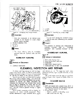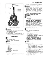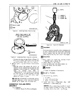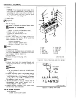
- Install the self-threading screw.
- Pry out plug.
Oil gallery screw plugs.
C le a n
• Sealing material from mating surfaces.
• Boil cylinder block in caustic solution.
- Flush with clean water or steam.
• Oil passages.
• All blind holes.
• Spray or wipe cylinder bores and machined
surfaces with engine oil.
} *
Inspect
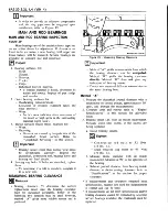
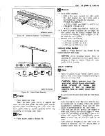
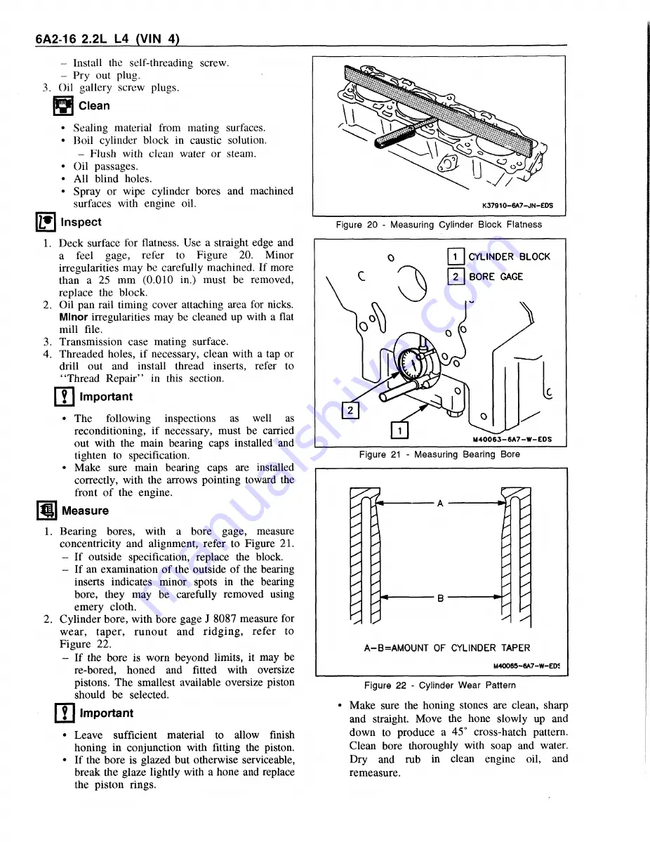
1. Deck surface for flatness. Use a straight edge and
a feel gage, refer to Figure 20. Minor
irregularities may be carefully machined. If more
than a 25 mm (0.010 in.) must be removed,
replace the block.
2. Oil pan rail timing cover attaching area for nicks.
Minor
irregularities may be cleaned up with a flat
mill file.
3. Transmission case mating surface.
4. Threaded holes, if necessary, clean with a tap or
drill out and install thread inserts, refer to
“ Thread Repair” in this section.
f f l Important
• The
following
inspections
as
well
as
reconditioning, if necessary, must be carried
out with the main bearing caps installed and
tighten to specification.
• Make sure main bearing caps are installed
correctly, with the arrows pointing toward the
front of the engine.
Measure
m
1.
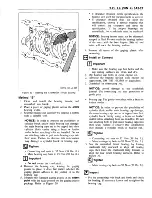
Bearing bores, with a bore gage, measure
concentricity and alignment, refer to Figure 21.
- If outside specification, replace the block.
- If an examination of the outside of the bearing
inserts indicates minor spots in the bearing
bore, they may be carefully removed using
emery cloth.
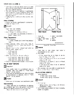
2. Cylinder bore, with bore gage J 8087 measure for
wear, taper, runout and ridging, refer to
Figure 22.
- If the bore is worn beyond limits, it may be
re-bored, honed and fitted with oversize
pistons. The smallest available oversize piston
should be selected.
m Important
Leave sufficient material to allow finish
honing in conjunction with fitting the piston.
If the bore is glazed but otherwise serviceable,
break the glaze lightly with a hone and replace
the piston rings.
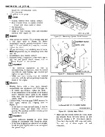
Figure 20 - Measuring Cylinder Block Flatness
A-B=AMOUNT OF CYLINDER TAPER
M40065-6A7-W-EDJ
Figure 22 - Cylinder Wear Pattern
• Make sure the honing stones are clean, sharp
and straight. Move the hone slowly up and
down to produce a 45° cross-hatch pattern.
Clean bore thoroughly with soap and water.
Dry and rub in clean engine oil, and
remeasure.
Summary of Contents for Light Duty Truck 1994 Series
Page 1: ......
Page 11: ...VIEW A p n n n j VIEW C F7554 Figure 10 Hydra Matic 4L60 E Transmission I D Location ...
Page 24: ...NOTES ...
Page 26: ... ...
Page 69: ...NOTES ...
Page 71: ...3 2 STEERING ...
Page 73: ......
Page 84: ......
Page 102: ...40 ...
Page 130: ...NOTES ...
Page 146: ...NOTES ...
Page 162: ...NOTES ...
Page 166: ...Figure 5 Removing the Pinion Flange Figure 6 Pressing the Drive Pinion from the Cage ...
Page 178: ...Figure 3 Spreading the Differential Case Figure 4 Removing the Differential ...
Page 190: ...NOTES ...
Page 202: ...NOTES ...
Page 206: ...F5785 ...
Page 212: ...B Button Moved Out of Bearing Bore F5791 ...
Page 228: ...NOTES ...
Page 232: ......
Page 234: ......
Page 236: ...Adjuster 63 Bolt 64 Lock Figure 10 Turning the Adjuster Plug K3 Models ...
Page 237: ...Figure 13 Removing the Pinion Seal 39 Bearing Cup Figure 16 Removing the Inner Bearing Cap ...
Page 261: ...F7475 ...
Page 267: ...B Button Moved Out of Bearing Bore F5791 ...
Page 294: ...NOTES ...
Page 300: ...NOTES ...
Page 318: ...NOTES ...
Page 322: ...SR207LN2 EDS ...
Page 324: ......
Page 326: ...OVERHEAD OILING AND RETURN MAIN OIL GALLERY N30005 6A2 J EDS ...
Page 368: ...103 153 127 V1200 ...
Page 370: ......
Page 372: ......
Page 374: ...F9375 Figure 7 Engine Lubrication Diagram Engines Without Balance Shaft ...
Page 376: ...Figure 9 Engine Lubrication Diagram Engines With Balance Shaft ...
Page 399: ...V2974 ...
Page 410: ......
Page 412: ...195 196 201 174 252 163 165 164 244 3706r3924 ...
Page 452: ......
Page 454: ...163 164 V1202 ...
Page 456: ...20 21x 302 210 4 0 41 2 5 2 5 1 2 51 4 2 e3 54 3 9 252 252 S 255 255 25 6 256 209 V1196 ...
Page 458: ...100 1 8 4 185 183 177 v 75 201 3706r1204 ...
Page 460: ......
Page 510: ......
Page 512: ...V2131 ...
Page 514: ...110 106 106 103 90 93 89 88 87 86 v 7 7 7 7 j A _ 111 f t 2 a a s 53 49 L 47 46 3706r4751 ...
Page 566: ...NOTES ...
Page 574: ...NOTES ...
Page 618: ...SPECIAL TOOLS ...
Page 620: ...NOTES ...
Page 672: ......
Page 682: ......
Page 686: ......
Page 694: ...RH0213 4L60 E ...
Page 695: ...657 659 m i J 8092 H J 34196 4 3 34196 5 657 658 665 J 23907 J 7004 1 J 8092 RH0214 4L60 E ...
Page 696: ...J 8092 J 34196 4 33 31 J 8092 RH0215 4L60 E ...
Page 697: ...SPECIAL TOOLS ...
Page 698: ...SPECIAL TOOLS ...
Page 758: ...RH0194 4L80 E ...
Page 764: ......
Page 770: ...SPECIAL TOOLS ...
Page 771: ...SPECIAL TOOLS CONT ...
Page 772: ......
Page 775: ......
Page 776: ......
Page 785: ......
Page 804: ...NOTES ...
Page 806: ......
Page 808: ......
Page 822: ...3707r5079 ...
Page 840: ......
Page 848: ...NOTES ...
Page 852: ......
Page 860: ...F5435 ...
Page 866: ......
Page 878: ...F9167 ...
Page 882: ...16 FrontOutputShaft 18 DrivtQNr 19 DrivenGm t 20 DriveChain 22 FrontOutputBearing V2836 ...
Page 890: ...F9168 ...
Page 908: ......
Page 919: ......

