Tighten
Important
• Bolt to 22 N.m (16 lbs. ft.).
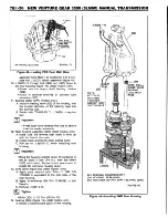
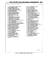
19. Position J 8763-21, J 8763-02, and J 36824 onto
the transmission case (figure 11).
20. Third-fourth shift fork (102) onto the third-fourth
synchronizer sleeve (8).
• Align all three insert notches.
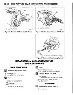
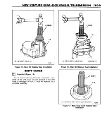
21. Shift shaft (108) into third-fourth shift fork (102)
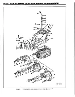
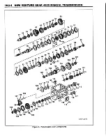
with detent reliefs in shaft pointing out (figures 1
and 2).
22. Shift lever (104) and block-out bushing (103) onto
the shift shaft (108).
23. Shift shaft (108) through first-second shift fork
(
101
).
24. Biasing spring (109), anti-rotation bracket (110),
and shift socket (114) onto the shift shaft (108).
•S lid e the shift shaft (108) all the way into the
case (300) or (301).
25. New roll pin (105) into shift lever.
• Rotate shift shaft and shift lever/blockout bush
ing assembly until roll pin holes are aligned and
horizontal.
• Install pin (105) until flush with the shift lever
(104).
26. Fork insert detent spring (106) and ball (107) into
hole in the shift lever (104).
• Rotate shift shaft (108) counter-clockwise until
shift lever (104) is almost into fifth-reverse
insert notch.
• Install spring (106) and ball (107) into shift lever
(104).
• Rotate shift shaft (108) until shift lever (104)
aligns with 3-4 insert.
27. Shift socket (114) to shift shaft roll pin (113).
•A lig n holes in the shift socket (114) and shift
shaft (108).
• Drive roll pin (113) until it is flush with the bot
tom of the shift socket (114).
Important
• Use the second (middle) roll pin hole on the
MG5 transmission and the rear roll pin hole on
the MY2 transmission.
28. Biasing spring (109) tangs to the anti-rotation
bracket (110) using a screw driver.
• Make sure the shifter is in neutral and anti-rota
tio n b ra c k e t ro lle rs (112) are le v e l w ith
machined surface of case opening.
29. Gasket eliminator to both sides of the anti-rotation
roller plate and install to case opening.
• Thin side of plate as viewed from the top
should be installed towards the left side of the
transmission.
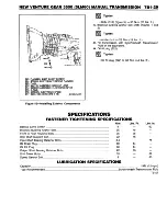
30. Shift tower (136) and bolts (204) (figure 33).
a
Tighten
• Shift tower bolts to 10 N-m (89 lbs. in.).
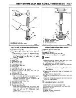
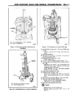
31. Countershaft bearing (35) to countershaft race (fig
ure 10).
A. Install smaller diameter of bearing cage into the
bearing race.
B. Press each roller into cage and retain with
TRANSJEL ™ J 36850 or equivalent.
C. Apply TRANSJEL ™ J 36850 or equivalent to
bearing race on input shaft.
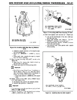
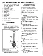
32. Front housing (200) (figure 10).
Important
• Bring the housing straight down. If resistance is
felt at about 7 mm (1/4 in.), then the rollers (35)
are cocked. Repeat steps 28, 29, and 30. Do
not force down the housing.
33. Two dowels (321) (figures 1 and 2).
34. Bolts (312) (figure 10).
• Do not tighten.
• Tip vertically.
35. NEW snap ring (210) (figure 9).
• It may be necessary to pull out on the input
shaft to install the snap ring.
• Apply gasket maker GM P/N 1052943 or equiv
alent to the inside of the bolt hole pattern.
Important
• DO NOT APPLY to o m uch g a ske t m aker
around the oil drain back hole. This could clog
the hole causing a low fluid flow through the
bearing resulting in premature bearing failure.
36. Input shaft bearing retainer assembly (205) and six
bolts (204).
• Make sure oil drain back hole is lined up with
the hole in the housing.
$
Tighten
• Bolts (204) to 8.5 N-m (75 lbs. in.).
37. Shift shaft detent plunger (243), shift shaft detent
spring (244), and plug (245) using brass drift (fig
ure 53).
• Apply pipe sealant with Teflon ™ GM P/N
1052080 or equivalent to the plug.
38. Install new O-ring (315) onto electronic speed sen
sor assembly (316) (2WD models only).
• Coat the O-ring with a thin film of transmission
fluid.
39. Electronic speed sensor assembly (316) and bolt
(317) (2WD models only).
Tighten
• Bolt (317) to 9 N-m (80 lbs. in.).
40. Backup lamp switch assembly (313).
• A pply pipe sealant with Teflon ™ GM P/N
1052080 or equivalent to the threads.
&
Tighten
• Switch (313) to 9 N-m (80 lbs. in.).
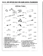
41. Remove J 8763-02 and J 36824.
Summary of Contents for Light Duty Truck 1994 Series
Page 1: ......
Page 11: ...VIEW A p n n n j VIEW C F7554 Figure 10 Hydra Matic 4L60 E Transmission I D Location ...
Page 24: ...NOTES ...
Page 26: ... ...
Page 69: ...NOTES ...
Page 71: ...3 2 STEERING ...
Page 73: ......
Page 84: ......
Page 102: ...40 ...
Page 130: ...NOTES ...
Page 146: ...NOTES ...
Page 162: ...NOTES ...
Page 166: ...Figure 5 Removing the Pinion Flange Figure 6 Pressing the Drive Pinion from the Cage ...
Page 178: ...Figure 3 Spreading the Differential Case Figure 4 Removing the Differential ...
Page 190: ...NOTES ...
Page 202: ...NOTES ...
Page 206: ...F5785 ...
Page 212: ...B Button Moved Out of Bearing Bore F5791 ...
Page 228: ...NOTES ...
Page 232: ......
Page 234: ......
Page 236: ...Adjuster 63 Bolt 64 Lock Figure 10 Turning the Adjuster Plug K3 Models ...
Page 237: ...Figure 13 Removing the Pinion Seal 39 Bearing Cup Figure 16 Removing the Inner Bearing Cap ...
Page 261: ...F7475 ...
Page 267: ...B Button Moved Out of Bearing Bore F5791 ...
Page 294: ...NOTES ...
Page 300: ...NOTES ...
Page 318: ...NOTES ...
Page 322: ...SR207LN2 EDS ...
Page 324: ......
Page 326: ...OVERHEAD OILING AND RETURN MAIN OIL GALLERY N30005 6A2 J EDS ...
Page 368: ...103 153 127 V1200 ...
Page 370: ......
Page 372: ......
Page 374: ...F9375 Figure 7 Engine Lubrication Diagram Engines Without Balance Shaft ...
Page 376: ...Figure 9 Engine Lubrication Diagram Engines With Balance Shaft ...
Page 399: ...V2974 ...
Page 410: ......
Page 412: ...195 196 201 174 252 163 165 164 244 3706r3924 ...
Page 452: ......
Page 454: ...163 164 V1202 ...
Page 456: ...20 21x 302 210 4 0 41 2 5 2 5 1 2 51 4 2 e3 54 3 9 252 252 S 255 255 25 6 256 209 V1196 ...
Page 458: ...100 1 8 4 185 183 177 v 75 201 3706r1204 ...
Page 460: ......
Page 510: ......
Page 512: ...V2131 ...
Page 514: ...110 106 106 103 90 93 89 88 87 86 v 7 7 7 7 j A _ 111 f t 2 a a s 53 49 L 47 46 3706r4751 ...
Page 566: ...NOTES ...
Page 574: ...NOTES ...
Page 618: ...SPECIAL TOOLS ...
Page 620: ...NOTES ...
Page 672: ......
Page 682: ......
Page 686: ......
Page 694: ...RH0213 4L60 E ...
Page 695: ...657 659 m i J 8092 H J 34196 4 3 34196 5 657 658 665 J 23907 J 7004 1 J 8092 RH0214 4L60 E ...
Page 696: ...J 8092 J 34196 4 33 31 J 8092 RH0215 4L60 E ...
Page 697: ...SPECIAL TOOLS ...
Page 698: ...SPECIAL TOOLS ...
Page 758: ...RH0194 4L80 E ...
Page 764: ......
Page 770: ...SPECIAL TOOLS ...
Page 771: ...SPECIAL TOOLS CONT ...
Page 772: ......
Page 775: ......
Page 776: ......
Page 785: ......
Page 804: ...NOTES ...
Page 806: ......
Page 808: ......
Page 822: ...3707r5079 ...
Page 840: ......
Page 848: ...NOTES ...
Page 852: ......
Page 860: ...F5435 ...
Page 866: ......
Page 878: ...F9167 ...
Page 882: ...16 FrontOutputShaft 18 DrivtQNr 19 DrivenGm t 20 DriveChain 22 FrontOutputBearing V2836 ...
Page 890: ...F9168 ...
Page 908: ......
Page 919: ......


