CLUTCHES AND TRANSMISSIONS 7-21
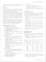
level dip stick is located at the right rear of the engine
compartment. Fill with oil specified in Section 0.
In order to check oil level accurately, the engine should
be idled with the transmission oil hot and the control
lever in neutral (N) position.
It is important that the oil level be maintained no
higher than the “ FULL” mark on the transmission oil
level gauge. DO NOT OVERFILL, for when the oil level
is at the full mark on the dip stick, it is just slightly be
low the planetary gear unit. If additional oil is added,
bringing the oil level above the full mark, the planetary
unit will run in the oil, foaming and aerating the oil. This
aerated oil carried through the various oil pressure pas
sages (low servo, reverse servo, clutch apply, converter,
etc.) may cause malfunction of the transmission assem
bly, resulting in cavitation noise in the converter and
improper band or clutch application. Overheating might
also occur.
If the transmission is found consistently low on oil, a
thorough inspection should be made to find and correct
all external oil leaks.
PERIODIC OIL CH AN G E
The transmission oil should be changed periodically as
recommended in Section 0, and whenever transmission is
to be removed from the vehicle for repairs.
1. Run engine fo r one minute in neutral prior to
changing.
2. Be sure vehicle is level or raise from the rear only.
3. Remove the oil pan drain plug and allow oil to drain
thoroughly into a pan or can.
4. Replace drain plug and refill with approximately two
and one half quarts of oil specified in Section 0.
NOTE:
To refill the transmission, remove dip
stick from oil filler tube and refill transmission
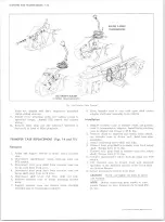
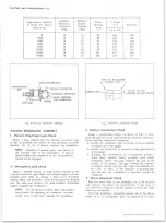
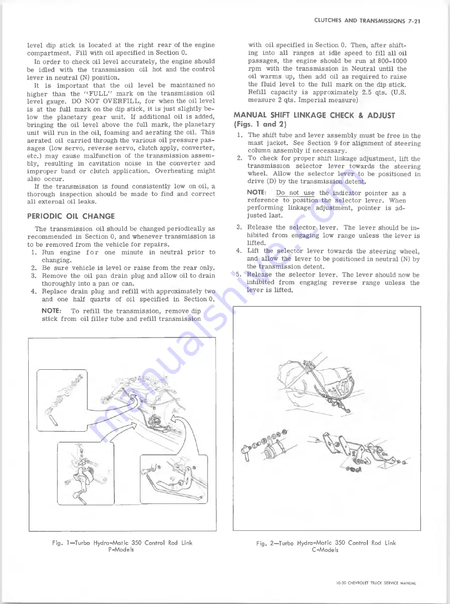
Fig. 1— 'Turbo H yd ra-M atic 350 Control Rod Link
P-M od els
with oil specified in Section 0. Then, after shift
ing into all ranges at idle speed to fill all oil
passages, the engine should be run at 800-1000
rpm with the transmission in Neutral until the
oil warms up, then add oil as required to raise
the fluid level to the full mark on the dip stick.
Refill capacity is approximately 2.5 qts. (U.S.
measure 2 qts. Imperial measure)
M A N U A L SHIFT LINKAGE CHECK & ADJUST
(Figs. 1 and 2)
1. The shift tube and lever assembly must be free in the
mast jacket. See Section 9 for alignment of steering
column assembly if necessary.
2. To check for proper shift linkage adjustment, lift the
transmission selector lever towards the steering
wheel. Allow the selector lever to be positioned in
drive (D) by the transmission detent.
NOTE:
Do not use the indicator pointer as a
reference to position the selector lever. When
performing linkage adjustment, pointer is ad
justed last.
3. Release the selector lever. The lever should be in
hibited from engaging low range unless the lever is
lifted.
4. Lift the selector lever towards the steering wheel,
and allow the lever to be positioned in neutral (N) by
the transmission detent.
5. Release the selector lever. The lever should now be
inhibited from engaging reverse range unless the
lever is lifted.
Fig. 2— Turbo H ydra-M atic 350 Control Rod Link
C -M o d e Is
10-30 CHEVROLET TRUCK SERVICE MANUAL
Summary of Contents for 10 1971 Series
Page 1: ......
Page 96: ......
Page 100: ...10 30 CHEVROLET TRUCK SERVICE MANUAL Fig 4 10 30 Series Truck Frame FRAME 2 4 ...
Page 120: ......
Page 203: ...ENGINE 6 25 Fig 22L Engine Mounts 10 30 CHEVROLET TRUCK SERVICE MANUAL ...
Page 215: ...ENGINE 6 37 REAR M O U NT Fig 21V Engine Mounts 10 30 CHEVROLET TRUCK SERVICE MANUAL ...
Page 218: ......
Page 249: ......
Page 324: ......
Page 340: ......
Page 365: ...10 30 CHEVROLET TRUCK SERVICE MANUAL Fig 43 Power Steering Pump M ounting STEERING 9 25 ...
Page 368: ......
Page 386: ......
Page 390: ...ELECTRICAL BODY AND CHASSIS 12 4 10 30 CHEVROLET TRUCK SERVICE MANUAL ...
Page 391: ......
Page 428: ......
Page 432: ......
Page 449: ...SPECIFICATIONS 9 10 30 CHEVROLET TRUCK SERVICE MANUAL ...
Page 463: ......
Page 464: ......
Page 465: ......
Page 466: ......


