ELECTRICAL— BODY AND CHASSIS 12-12
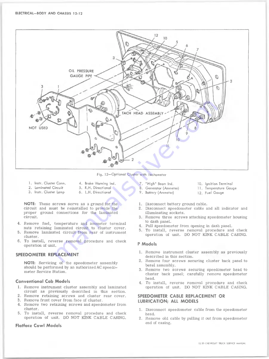
OIL PRESSURE
GAUGE PIPE
NOT USED
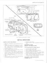
Fig. 12— Optional Cluster with Tachometer
Brake Warning Ind.
R.H. Directional
L„H0 Directional
7. "H ig h " Beam Ind.
8. Generator (Ammeter)
9. Battery (Ammeter)
10. Ignition Terminal
11. Temperature Gauge
12. Fuel Gauge
NOTE:
These screws serve as a ground for the
circuit and must be reinstalled to provide the
proper ground connections for the laminated
circuit.
4. Remove fuel, temperature and ammeter terminal
nuts retaining laminated circuit to cluster cover.
5. Remove laminated circuit from rear of instrument
cluster.
6. To install, reverse removal procedure and check
operation of unit.
SPEEDOMETER REPLACEMENT
NOTE:
Servicing of the speedometer assembly
should be performed by an authorized AC speedo
meter Service Station.
Conventional Cab Models
1. Remove instrument cluster assembly and laminated
circuit as previously described in this section.
2. Remove retaining screws and cluster rear cover.
3. Remove front cover from face of cluster.
4. Remove two retaining screws and speedometer from
cluster.
5. To install, reverse removal procedure and check
operation of unit. DO NOT KINK CABLE CASING.
Flatface Cowl Models
1. Disconnect battery ground cable.
2. Disconnect speedometer cable and all indicator and
illuminating sockets.
3. Remove three screws attaching speedometer housing
to dash panel.
4. Pull speedometer from opening in dash panel.
5. To install, reverse removal procedure and check
operation of unit. DO NOT KINK CABLE CASING.
P Models
1. Remove instrument cluster assembly as previously
described in this section.
2. Remove four screws securing cluster back panel to
bezel assembly.
3. Remove two screws securing speedometer head to
cluster back panel; carefully remove speedometer
head.
4. To install, reverse removal procedure and check
operation of unit. DO NOT KINK CABLE CASING.
SPEEDOMETER CABLE REPLACEMENT OR
LUBRICATION; ALL MODELS
1. Disconnect speedometer cable from the speedometer
head.
2. Remove old cable by pulling it out from speedometer
end of casing.
10-30 CHEVROLET TRUCK SERVICE MANUAL
Summary of Contents for 10 1971 Series
Page 1: ......
Page 96: ......
Page 100: ...10 30 CHEVROLET TRUCK SERVICE MANUAL Fig 4 10 30 Series Truck Frame FRAME 2 4 ...
Page 120: ......
Page 203: ...ENGINE 6 25 Fig 22L Engine Mounts 10 30 CHEVROLET TRUCK SERVICE MANUAL ...
Page 215: ...ENGINE 6 37 REAR M O U NT Fig 21V Engine Mounts 10 30 CHEVROLET TRUCK SERVICE MANUAL ...
Page 218: ......
Page 249: ......
Page 324: ......
Page 340: ......
Page 365: ...10 30 CHEVROLET TRUCK SERVICE MANUAL Fig 43 Power Steering Pump M ounting STEERING 9 25 ...
Page 368: ......
Page 386: ......
Page 390: ...ELECTRICAL BODY AND CHASSIS 12 4 10 30 CHEVROLET TRUCK SERVICE MANUAL ...
Page 391: ......
Page 428: ......
Page 432: ......
Page 449: ...SPECIFICATIONS 9 10 30 CHEVROLET TRUCK SERVICE MANUAL ...
Page 463: ......
Page 464: ......
Page 465: ......
Page 466: ......


