REAR SUSPENSION AND DRIVE LINE 4-2
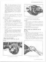
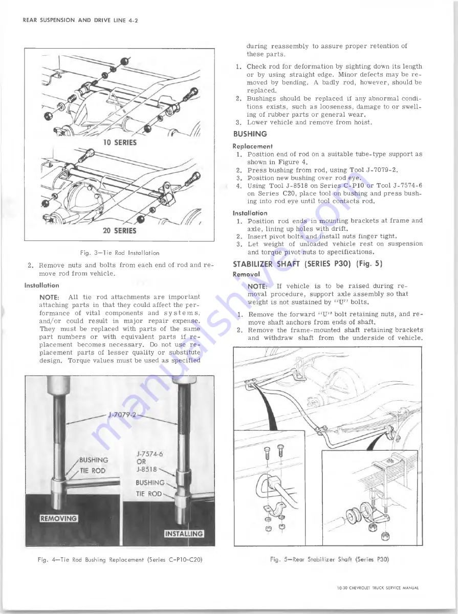
Fig. 3— Tie Rod Installation
2. Remove nuts and bolts from each end of rod and re
move rod from vehicle.
installation
NOTE:
All tie rod attachments are important
attaching parts in that they could affect the per
formance of vital components and s y s t e ms ,
and/or could result in major repair expense.
They must be replaced with parts of the same
part numbers or with equivalent parts if re
placement becomes necessary. Do not use re
placement parts of lesser quality or substitute
design. Torque values must be used as specified
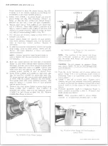
Fig. 4— Tie Rod Bushing Replacement (Series C -P 1 0 -C 2 0 )
during reassembly to assure proper retention of
these parts.
1. Check rod for deformation by sighting down its length
or by using straight edge. Minor defects may be re
moved by bending. A badly rod, however, should be
replaced.
2. Bushings should be replaced if any abnormal condi
tions exists, such as looseness, damage to or swell
ing of rubber parts or general wear.
3. Lower vehicle and remove from hoist.
BUSHING
Replacement
1. Position end of rod on a suitable tube-type support as
shown in Figure 4.
2. Press bushing from rod, using Tool J-7079-2.
3. Position new bushing over rod eye.
4. Using Tool J-8518 on Series C-P10 or Tool J-7574-6
on Series C20, place tool on bushing and press bush
ing into rod eye until tool contacts rod.
Installation
1. Position rod ends in mounting brackets at frame and
axle, lining up holes with drift.
2„ Insert pivot bolts and install nuts finger tight.
3. Let weight of unloaded vehicle rest on suspension
and torque pivot nuts to specifications.
STABILIZER SHAFT (SERIES P30) (Fig. 5)
Removal
NOTE:
If vehicle is to be raised during re
moval procedure, support axle assembly so that
weight is not sustained by
bolts.
1. Remove the forward
bolt retaining nuts, and re
move shaft anchors from ends of shaft.
2. Remove the frame-mounted shaft retaining brackets
and withdraw shaft from the underside of vehicle.
10-30 CHEVROLET TRUCK SERVICE MANUAL
Summary of Contents for 10 1971 Series
Page 1: ......
Page 96: ......
Page 100: ...10 30 CHEVROLET TRUCK SERVICE MANUAL Fig 4 10 30 Series Truck Frame FRAME 2 4 ...
Page 120: ......
Page 203: ...ENGINE 6 25 Fig 22L Engine Mounts 10 30 CHEVROLET TRUCK SERVICE MANUAL ...
Page 215: ...ENGINE 6 37 REAR M O U NT Fig 21V Engine Mounts 10 30 CHEVROLET TRUCK SERVICE MANUAL ...
Page 218: ......
Page 249: ......
Page 324: ......
Page 340: ......
Page 365: ...10 30 CHEVROLET TRUCK SERVICE MANUAL Fig 43 Power Steering Pump M ounting STEERING 9 25 ...
Page 368: ......
Page 386: ......
Page 390: ...ELECTRICAL BODY AND CHASSIS 12 4 10 30 CHEVROLET TRUCK SERVICE MANUAL ...
Page 391: ......
Page 428: ......
Page 432: ......
Page 449: ...SPECIFICATIONS 9 10 30 CHEVROLET TRUCK SERVICE MANUAL ...
Page 463: ......
Page 464: ......
Page 465: ......
Page 466: ......


