REAR SUSPENSION AND DRIVE LINE 4-22
PROPELLER SHAFT AND UNIVERSAL JOINTS
INDEX
Page
Component Parts Replacement ............................................................
Removal ............................................................................................
...........................................................
Center Support B e aring s ................................................................
Page
I
Installation .......................................................................................
Constant Velocity Joint .....................................................................
Disassembly.......................................................................................
Assembly...........................................................................................
Specifications .....................................................(See Specifications Section)
SERVICE INFORMATION
Both one piece and two piece propeller shafts are used
depending on the model. All are tubular and use needle
bearing type universal joints.
On models that use a two piece shaft, the shaft is sup
ported near its splined end in a rubber cushioned ball
bearing which is mounted in a bracket attached to a
frame crossmember. The ball bearing is permanently
lubricated and sealed.
Four wheel drive models use a front propeller shaft
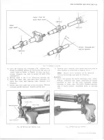
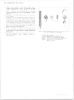
incorporating a constant velocity joint (fig. 53).
COMPONENT PART REPLACEMENT
PROPELLER SHAFT
Two methods are used to retain the propeller shaft
to the differential pinion flange. One method utilizes
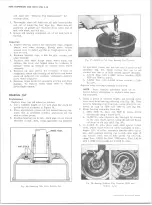
“ U” bolts (fig. 45) and the other is a strap attachment
(fig. 46).
Removal
1. Raise vehicle on hoist. Mark relationship of shaft
to companion flange and disconnect the rear uni
versal joint by removing trunnion bearing
“ V”
bolts or straps. Tape bearing cups to trunnion to
prevent dropping and loss of bearing rollers.
2. For models with two-piece shafts remove bolts re
taining bearing support to frame crossmember.
3. Slide propeller shaft forward disengaging trunnion
from axle flange, then slide assembly rearward
disengaging from transmission.
Repairs (Universal Joints)
NOTE:
The universal joints are of the
extended-life design and do not require periodic
inspection or lubrication; however, when these
Fig. 45— “ U ” Bolt Attachment
joints are disassembled, repack bearings and
lubricate reservoir at end of trunnions with
high-melting point wheel bearing lubricant and
replace the dust seals.
1. Remove bearing lock rings from trunnion yoke.
2. Support trunnion yoke on a piece of 1-1/4" I0D.
pipe on an arbor bed.
NOTE:
Due to length of the propeller shaft
it may be more convenient to use a bench vise,
for removal and installation, instead of an arbor
press. In this case, proceed with disassembly
and assembly procedure as with an arbor press.
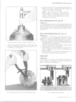
3. Using a suitable socket or rod, press on trunnion
until bearing cup is almost out (fig. 47). Grasp cup
in vise and work cup out of yoke.
NOTE:
The bearing cup cannot be fully pressed
out.
10-30 CHEVROLET TRUCK SERVICE MANUAL
Summary of Contents for 10 1971 Series
Page 1: ......
Page 96: ......
Page 100: ...10 30 CHEVROLET TRUCK SERVICE MANUAL Fig 4 10 30 Series Truck Frame FRAME 2 4 ...
Page 120: ......
Page 203: ...ENGINE 6 25 Fig 22L Engine Mounts 10 30 CHEVROLET TRUCK SERVICE MANUAL ...
Page 215: ...ENGINE 6 37 REAR M O U NT Fig 21V Engine Mounts 10 30 CHEVROLET TRUCK SERVICE MANUAL ...
Page 218: ......
Page 249: ......
Page 324: ......
Page 340: ......
Page 365: ...10 30 CHEVROLET TRUCK SERVICE MANUAL Fig 43 Power Steering Pump M ounting STEERING 9 25 ...
Page 368: ......
Page 386: ......
Page 390: ...ELECTRICAL BODY AND CHASSIS 12 4 10 30 CHEVROLET TRUCK SERVICE MANUAL ...
Page 391: ......
Page 428: ......
Page 432: ......
Page 449: ...SPECIFICATIONS 9 10 30 CHEVROLET TRUCK SERVICE MANUAL ...
Page 463: ......
Page 464: ......
Page 465: ......
Page 466: ......


