REAR SUSPENSION AN D DRIVE LINE 4-24
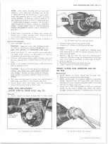
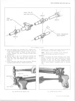
Fig. 50— Propeller Shaft, Universal Joint and Bearing Support
NOTE:
This propeller shaft to pinion flange
fastener is an important attaching part in that it
could affect the performance of vital components
and systems, and/or could result in major re
pair expense. It must be replaced with one of
the same part number or with an equivalent
part if replacement becomes necessary. Do not
use a replacement part of lesser quality or sub
stitute design. Torque values must be used as
specified during reassembly to assure proper
retention of this part.
2. For models with two piece shafts, install front half
into transmission and bolt support to crossmember.
a. Slide grease cap and gasket onto rear splines.
b. Rotate shaft so front U-joint trunnion is in a
vertical position.
c. Take rear propeller shaft and before installing
align U-joint trunnions in same vertical position
as in step b (at this point all U-joint trunnions
should be vertical), (fig. 51). Then, note rela
tionship of front shaft and rear shaft spline po
sition. For all models except model CE31403
(157" W„B. 307 CIO, V-8 Engine) Rotate rear
shaft four splines toward left side of vehicle
(fig. 42) and install rear shaft to front shaft. For
Model CE31403 rotate 2 splines. Attach rear
U-joint to axle. Tighten grease cap.
d. Torque bearing support to crossmember and U-
joint to axle attachments to specifications.
CONSTANT VELOCITY UNIVERSAL JOINT
Disassembly
1. Remove front propeller shaft from vehicle.
2. Remove rear trunnion snap rings from center yoke.
Remove grease fitting.
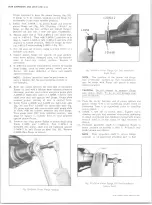
3. Place prop shaft in vice as shown in Figure 52.
Drive one rear trunnion bearing cap from center
yoke as shown in Figure 52 until it protrudes approx
imately 3/8".
NOTE:
Keep rear portion of propeller shaft up
to avoid interference of rear yoke half with
center yoke.
10-30 CHEVROLET TRUCK SERVICE MANUAL
Summary of Contents for 10 1971 Series
Page 1: ......
Page 96: ......
Page 100: ...10 30 CHEVROLET TRUCK SERVICE MANUAL Fig 4 10 30 Series Truck Frame FRAME 2 4 ...
Page 120: ......
Page 203: ...ENGINE 6 25 Fig 22L Engine Mounts 10 30 CHEVROLET TRUCK SERVICE MANUAL ...
Page 215: ...ENGINE 6 37 REAR M O U NT Fig 21V Engine Mounts 10 30 CHEVROLET TRUCK SERVICE MANUAL ...
Page 218: ......
Page 249: ......
Page 324: ......
Page 340: ......
Page 365: ...10 30 CHEVROLET TRUCK SERVICE MANUAL Fig 43 Power Steering Pump M ounting STEERING 9 25 ...
Page 368: ......
Page 386: ......
Page 390: ...ELECTRICAL BODY AND CHASSIS 12 4 10 30 CHEVROLET TRUCK SERVICE MANUAL ...
Page 391: ......
Page 428: ......
Page 432: ......
Page 449: ...SPECIFICATIONS 9 10 30 CHEVROLET TRUCK SERVICE MANUAL ...
Page 463: ......
Page 464: ......
Page 465: ......
Page 466: ......


