CLUTCHES AND TRANSMISSIONS 7-4
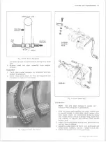
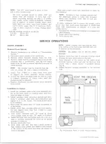
CLUTCH CROSS-SHAFT REPLACEMENT (Figs. 1 and 2)
Removal
1. Disconnect clutch fork return spring at fork.
2. Disconnect pedal push rod at cross-shaft lever and
allow clutch fork push rod to hang free from lower
lever.
3. Loosen ball stud nut and slide stud out of bracket
slot, then lift cross-shaft off engine ball stud and out
of vehicle.
4. Remove clutch fork push rod from cross-shaft lever
if necessary.
5. Reverse removal procedure to install.
Page
Clutch Assembly ................................................................................
Removal from V ehicle.....................................................................
Installation to V e h icle .....................................................................
CLUTCHES
DIAPHRAGM SPRING CLUTCH
INDEX
Page
M AINTENANCE A N D ADJUSTMENTS
PRELIMINARY INSPECTION
There are many things which affect good clutch opera
tion. Therefore, it is necessary, before performing any
major clutch operations, to make a preliminary inspec
tion to determine whether or not the trouble is actually in
the clutch.
1. Check the clutch pedal and make sure that the pedal
has at least 3/4"-l" free travel.
2. Check the clutch pedal bushing for wear and for
sticking on the shaft or loose mountings.
3. Lubricate the pedal linkage.
4. Tighten all front and rear engine mounting bolts.
Should the mountings be oil soaked, it will be neces
sary to replace them.
CLUTCH RETRACTING SPRING REPLACEMENT
A rattle in the clutch assembly at idling speeds with the
clutch released or failure of the clutch to release prop
erly may be caused by insufficient tension on the pres
sure plate retracting springs. These troubles can easily
be checked by replacing the springs, as follows:
1. Remove the clutch housing underpan.
2. Hand crank the engine until one retracting spring at
taching bolt is at the bottom. Remove the bolt and
retracting spring and install a new spring.
3. Replace the other retracting springs in the same
manner.
4. Replace clutch housing underpan.
DIAPH R AG M CLUTCH ADJUSTMENT
If clutch fails to release:
1. Check pedal for proper travel and linkage for loose
ness, adjustments, lost motion, etc.
2. Check clutch retracting springs for proper retention
of pressure plate to diaphragm spring, replace if
necessary. This can be done without removing clutch
from vehicle.
3. If Steps 1 and 2 do not cure trouble, check pressure
plate lift with dial indicator (fig. 7) as follows:
a. With proper linkage adjustment (and lash), zero
indicator with clutch fully engaged (pedal up).
b. Measure pressure plate lift at 3 strap bolt posi
tions with full pedal travel.
Fig. 6— C h e ck in g Pressure Plate Lift w /dial Indicator
Fig. 7— G a u g in g Shim Requirement
10-30 CHEVROLET TRUCK SERVICE MANUAL
Summary of Contents for 10 1971 Series
Page 1: ......
Page 96: ......
Page 100: ...10 30 CHEVROLET TRUCK SERVICE MANUAL Fig 4 10 30 Series Truck Frame FRAME 2 4 ...
Page 120: ......
Page 203: ...ENGINE 6 25 Fig 22L Engine Mounts 10 30 CHEVROLET TRUCK SERVICE MANUAL ...
Page 215: ...ENGINE 6 37 REAR M O U NT Fig 21V Engine Mounts 10 30 CHEVROLET TRUCK SERVICE MANUAL ...
Page 218: ......
Page 249: ......
Page 324: ......
Page 340: ......
Page 365: ...10 30 CHEVROLET TRUCK SERVICE MANUAL Fig 43 Power Steering Pump M ounting STEERING 9 25 ...
Page 368: ......
Page 386: ......
Page 390: ...ELECTRICAL BODY AND CHASSIS 12 4 10 30 CHEVROLET TRUCK SERVICE MANUAL ...
Page 391: ......
Page 428: ......
Page 432: ......
Page 449: ...SPECIFICATIONS 9 10 30 CHEVROLET TRUCK SERVICE MANUAL ...
Page 463: ......
Page 464: ......
Page 465: ......
Page 466: ......


