CLUTCHES AND TRANSMISSIONS 7-20
TURBO HYDRA-MATIC 3 5 0 TRANSMISSION
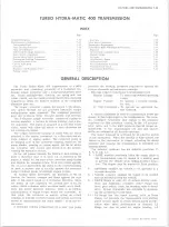
INDEX
Page
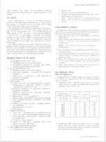
O il Level Check ......................................................................................... 7-20
Periodic O il Change ..................................................................................7-21
Manual Shift Linkage Check and A d justm e n t................................ ......7-21
Page
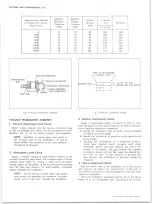
Turbo Hydra-Matic Diagnosis Procedure ........................................... ......7-24
Sequence ....................................................................................................7-24
O il Level and Condition C h e c k ......................................................... ......7-24
Manual Linkage .................................................................................. ......7-24
O il Leaks .............................................................................................. ......7-25
Case Porosity Repair ......................................................................... ......7-25
Vacuum Modulator Checks .............................................................. ......7-26
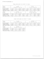
Transmission Shift P o in ts ........................................................................7-27
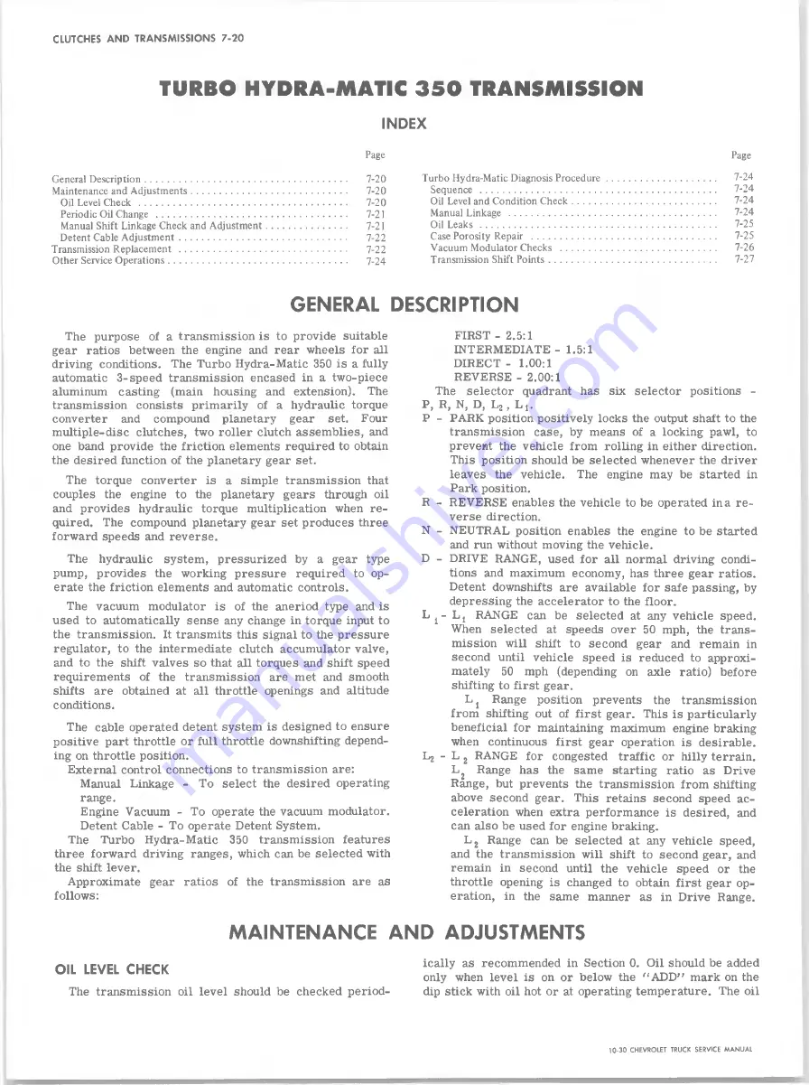
GENERAL DESCRIPTION
The purpose of a transmission is to provide suitable
gear ratios between the engine and rear wheels for all
driving conditions. The Turbo Hydra-Matic 350 is a fully
automatic 3-speed transmission encased in a two-piece
aluminum casting (main housing and extension). The
transmission consists primarily of a hydraulic torque
converter and compound planetary gear set. Four
multiple-disc clutches, two roller clutch assemblies, and
one band provide the friction elements required to obtain
the desired function of the planetary gear set.
The torque converter is a simple transmission that
couples the engine to the planetary gears through oil
and provides hydraulic torque multiplication when re
quired. The compound planetary gear set produces three
forward speeds and reverse.
The hydraulic system, pressurized by a gear type
pump, provides the working pressure required to op
erate the friction elements and automatic controls.
The vacuum modulator is of the aneriod type and is
used to automatically sense any change in torque input to
the transmission. It transmits this signal to the pressure
regulator, to the intermediate clutch accumulator valve,
and to the shift valves so that all torques and shift speed
requirements of the transmission are met and smooth
shifts are obtained at all throttle openings and altitude
conditions.
The cable operated detent system is designed to ensure
positive part throttle or full throttle downshifting depend
ing on throttle position.
External control connections to transmission are:
Manual Linkage - To select the desired operating
range.
Engine Vacuum - To operate the vacuum modulator.
Detent Cable - To operate Detent System.
The Turbo Hydra-Matic 350 transmission features
three forward driving ranges, which can be selected with
the shift lever.
Approximate gear ratios of the transmission are as
follows:
FIRST - 2.5:1
INTERMEDIATE - 1.5:1
DIRECT - 1.00:1
REVERSE - 2.00:1
The selector quadrant has six selector positions -
P, R, N, D, L2, L 1#
P - PARK position positively locks the output shaft to the
transmission case, by means of a locking pawl, to
prevent the vehicle from rolling in either direction.
This position should be selected whenever the driver
leaves the vehicle. The engine may be started in
Park position.
R - REVERSE enables the vehicle to be operated in a re
verse direction.
N - NEUTRAL position enables the engine to be started
and run without moving the vehicle.
D - DRIVE RANGE, used for all normal driving condi
tions and maximum economy, has three gear ratios.
Detent downshifts are available for safe passing, by
depressing the accelerator to the floor.
L j - Lj RANGE can be selected at any vehicle speed.
When selected at speeds over 50 mph, the trans
mission will shift to second gear and remain in
second until vehicle speed is reduced to approxi
mately 50 mph (depending on axle ratio) before
shifting to first gear.
L 1 Range position prevents the transmission
from shifting out of first gear. This is particularly
beneficial for maintaining maximum engine braking
when continuous first gear operation is desirable.
L2 - L 2 RANGE for congested traffic or hilly terrain.
L 2 Range has the same starting ratio as Drive
Range, but prevents the transmission from shifting
above second gear. This retains second speed ac
celeration when extra performance is desired, and
can also be used for engine braking.
L 2 Range can be selected at any vehicle speed,
and the transmission will shift to second gear, and
remain in second until the vehicle speed or the
throttle opening is changed to obtain first gear op
eration, in the same manner as in Drive Range.
M AIN TENANCE A N D ADJUSTMENTS
OIL LEVEL CHECK
The transmission oil level should be checked period
ically as recommended in Section 0. Oil should be added
only when level is on or below the “ ADD” mark on the
dip stick with oil hot or at operating temperature. The oil
10-30 CHEVROLET TRUCK SERVICE MANUAL
Summary of Contents for 10 1971 Series
Page 1: ......
Page 96: ......
Page 100: ...10 30 CHEVROLET TRUCK SERVICE MANUAL Fig 4 10 30 Series Truck Frame FRAME 2 4 ...
Page 120: ......
Page 203: ...ENGINE 6 25 Fig 22L Engine Mounts 10 30 CHEVROLET TRUCK SERVICE MANUAL ...
Page 215: ...ENGINE 6 37 REAR M O U NT Fig 21V Engine Mounts 10 30 CHEVROLET TRUCK SERVICE MANUAL ...
Page 218: ......
Page 249: ......
Page 324: ......
Page 340: ......
Page 365: ...10 30 CHEVROLET TRUCK SERVICE MANUAL Fig 43 Power Steering Pump M ounting STEERING 9 25 ...
Page 368: ......
Page 386: ......
Page 390: ...ELECTRICAL BODY AND CHASSIS 12 4 10 30 CHEVROLET TRUCK SERVICE MANUAL ...
Page 391: ......
Page 428: ......
Page 432: ......
Page 449: ...SPECIFICATIONS 9 10 30 CHEVROLET TRUCK SERVICE MANUAL ...
Page 463: ......
Page 464: ......
Page 465: ......
Page 466: ......


