9. Reassemble the pitman arm to the pitman shaft,
lining up the marks made during disassembly.
Tighten the pitman shaft nut to specifications.
CAUTION:
If a clamp type pitman arm is used,
spread the pitman arm just enough, with a
wedge, to slip the arm onto the pitman shaft. Do
not spread the clamp more than required to slip
over pitman shaft with hand pressure. Do not
hammer the pitman arm onto the pitman shaft.
Be sure to install the hardened steel washer
before installing the nut.
10. Install the horn button cap and connect the battery
ground cable.
Steering Gear High Point Centering-C-P 10, C 20-30
1. Set front wheels in straight ahead position. This can
be checked by driving vehicle a short distance on a
flat surface to determine steering wheel position at
which vehicle follows a straight path.
2. With front wheels set straight ahead, check position
of mark on wormshaft designating steering gear high
point. This mark should be at the top side of the
shaft at 12 o'clock position and lined up with the
mark in the coupling lower clamp.
3. If gear has been moved off high point when setting
wheels in straight ahead position, loosen adjusting
sleeve clamps on both left and right hand tie rods,
then turn both sleeves an equal number of turns in
the same direction to bring gear back on high point.
CAUTION:
Turning the sleeves an unequal
number of turns or in different directions will
disturb the toe-in setting of the wheels.
4. Readjust toe-in as outlined in Section 3 (if necessary).
Steering Wheel Alignment
NOTE:
On C-P10-20-30 series units check
steering gear for high point centering before
checking steering wheel alignment.
1. Set wheels in straight ahead position by driving
vehicle a short distance.
STEERING 9-3
2. Note steering wheel position. If off more than 1 inch
from center (fig. 4), remove steering wheel as out
lined under "Steering Wheel - Removal"; reposition
and reinstall the wheel.
Steering Column Lower Bearing Adjustment
1. Loosen clamp on steering shaft.
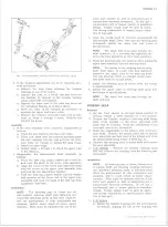
2. Applying 50 lb. force to the steering wheel end of the
steering shaft, adjust clamp to allow steering shaft
end play indicated in Figure 5.
3. Tighten clamp bolt to specified torque.
Shifter Tube Adjustment
3-Speed Transmission
1. Loosen adjusting ring attaching screws and clamp
bolt.
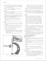
Fig. 6 — Shift Tube Adjustment — 3-Speed Transmission
10-30 CHEVROLET TRUCK SERVICE MANUAL
Summary of Contents for 10 1971 Series
Page 1: ......
Page 96: ......
Page 100: ...10 30 CHEVROLET TRUCK SERVICE MANUAL Fig 4 10 30 Series Truck Frame FRAME 2 4 ...
Page 120: ......
Page 203: ...ENGINE 6 25 Fig 22L Engine Mounts 10 30 CHEVROLET TRUCK SERVICE MANUAL ...
Page 215: ...ENGINE 6 37 REAR M O U NT Fig 21V Engine Mounts 10 30 CHEVROLET TRUCK SERVICE MANUAL ...
Page 218: ......
Page 249: ......
Page 324: ......
Page 340: ......
Page 365: ...10 30 CHEVROLET TRUCK SERVICE MANUAL Fig 43 Power Steering Pump M ounting STEERING 9 25 ...
Page 368: ......
Page 386: ......
Page 390: ...ELECTRICAL BODY AND CHASSIS 12 4 10 30 CHEVROLET TRUCK SERVICE MANUAL ...
Page 391: ......
Page 428: ......
Page 432: ......
Page 449: ...SPECIFICATIONS 9 10 30 CHEVROLET TRUCK SERVICE MANUAL ...
Page 463: ......
Page 464: ......
Page 465: ......
Page 466: ......


