CHASSIS SHEET METAL 11-2
SERVICE PROCEDURES
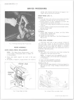
Fig. 2— Removing/Installing Hood Hinge Spring
HOOD ASSEMBLY
H O O D HINGE SPRING REPLACEMENT
NOTE:
For Hinge Spring Replacement, a tool
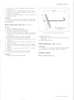
can be made to dimensions shown in Figure 12
for this purposec
1. Raise and safely support the hood in full open
position.
2. As shown in Figure 2, engage hooked end of tool to
spring, then carefully pull forward to engage or dis
engage spring from hinge assembly.
HOOD HINGE (FIG. 3)
Removal
1. Prop the hood in the extreme open position and place
protective covering over the cowl and fenders.
2. Scribe position of hinge attachment on hood rear
reinforcement and remove two bolts.
3. Remove hood hinge spring as explained in preceding
write-up.
4. Scribe position of hinge attachment on fender assem
bly and remove bolts.
5. Remove hinge.
Installation
1. Install hinge assembly to fender and align within
scribe marks. Install bolts.
2. Install hood hinge spring.
3. Install bolts and align hood. See Hood Alignment in
this section.
H O O D LOCK ASSEMBLY
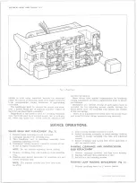
A bolt-type hood lock is used as shown in Figure 4.
The lock bolt, located on the hood dovetails with the
mounted striker plate, preventing upward or downward
movement of the hood while the vehicle is in motion.
Integral with the striker plate is the combination lock re
lease lever and safety catch.
Replacement
1. Open hood and remove the four bolts holding the
combination lock catch and lock bolt.
NOTE:
If original hood lock assembly is to be
replaced, scribe a line around lock for alignment
on installation.
2. Place hood lock assembly in position.
3. Adjust as outlined under Adjustments.
Adjustment (Fig. 6)
1. Open hood and adjust tightness of lock bolt support so
that they are just “ snug” enough to hold lock bolt in
position.
Fig. 4— Hood Striker and Safety Catch
10-30 CHEVROLET TRUCK SERVICE MANUAL
Summary of Contents for 10 1971 Series
Page 1: ......
Page 96: ......
Page 100: ...10 30 CHEVROLET TRUCK SERVICE MANUAL Fig 4 10 30 Series Truck Frame FRAME 2 4 ...
Page 120: ......
Page 203: ...ENGINE 6 25 Fig 22L Engine Mounts 10 30 CHEVROLET TRUCK SERVICE MANUAL ...
Page 215: ...ENGINE 6 37 REAR M O U NT Fig 21V Engine Mounts 10 30 CHEVROLET TRUCK SERVICE MANUAL ...
Page 218: ......
Page 249: ......
Page 324: ......
Page 340: ......
Page 365: ...10 30 CHEVROLET TRUCK SERVICE MANUAL Fig 43 Power Steering Pump M ounting STEERING 9 25 ...
Page 368: ......
Page 386: ......
Page 390: ...ELECTRICAL BODY AND CHASSIS 12 4 10 30 CHEVROLET TRUCK SERVICE MANUAL ...
Page 391: ......
Page 428: ......
Page 432: ......
Page 449: ...SPECIFICATIONS 9 10 30 CHEVROLET TRUCK SERVICE MANUAL ...
Page 463: ......
Page 464: ......
Page 465: ......
Page 466: ......


