ELECTRICAL— BODY AN D CHASSIS 12-10
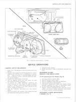
Fig. 10— Instrument Cluster Assembly - F/F Cowl
1. Open hood and remove ground cable from battery.
2. Standing outside vehicle reach up under instrument
cluster and disconnect speedometer cable by first
depressing tang on rear of speedometer head, pushing
then pulling cable free from head as tang is depressed.
3. Unplug instrument panel harness connector from
printed circuit.
4. Disconnect oil pressure line from gauge if so equip
ped. Place cloths beneath line connector to catch
drips.
5. Remove (2) two nuts attaching instrument cluster
studs to lower opening in instrument panel.
6. Pull top of cluster away from instrument panel and
lift out bottom of cluster.
7. Remove cluster to bench for futher disassembly
(laminated printed circuit, speedometer head, gauges).
Flatface Cowl Models (Fig. 10)
1. Disconnect battery ground cable.
2. Disconnect electrical connectors and oil pressure
pipe.
NOTE:
Oil pressure line connector may leak
oil when opened; wrap with cloth.
3. Remove three screws attaching cluster housing to
dash panel.
4. Pull cluster from opening in dash panel.
5. To install, reverse removal procedure.
INDICATOR A N D ILLUMINATING
BULB REPLACEMENT
10-30 Conventional Cab and P Models
1. Turn bulb holder counter-clockwise to remove from
the cluster housing.
2. Pull bulb straight out to remove from holder.
3. Install replacement bulb in holder, press inward to
lock in place.
4. Insert holder into housing, with lugs on holder enter
ing notches in case, and turn clockwise to lock in
place.
LAMINATED CIRCUIT REPLACEMENT
10-30 Conventional Cab Models (Fig. 11 & 12)
1. Remove instrument cluster assembly as previously
described in this section.
2. Remove all instrument cluster lamp assemblies.
3. Remove laminated circuit retaining screws.
10-30 CHEVROLET TRUCK SERVICE MANUAL
Summary of Contents for 10 1971 Series
Page 1: ......
Page 96: ......
Page 100: ...10 30 CHEVROLET TRUCK SERVICE MANUAL Fig 4 10 30 Series Truck Frame FRAME 2 4 ...
Page 120: ......
Page 203: ...ENGINE 6 25 Fig 22L Engine Mounts 10 30 CHEVROLET TRUCK SERVICE MANUAL ...
Page 215: ...ENGINE 6 37 REAR M O U NT Fig 21V Engine Mounts 10 30 CHEVROLET TRUCK SERVICE MANUAL ...
Page 218: ......
Page 249: ......
Page 324: ......
Page 340: ......
Page 365: ...10 30 CHEVROLET TRUCK SERVICE MANUAL Fig 43 Power Steering Pump M ounting STEERING 9 25 ...
Page 368: ......
Page 386: ......
Page 390: ...ELECTRICAL BODY AND CHASSIS 12 4 10 30 CHEVROLET TRUCK SERVICE MANUAL ...
Page 391: ......
Page 428: ......
Page 432: ......
Page 449: ...SPECIFICATIONS 9 10 30 CHEVROLET TRUCK SERVICE MANUAL ...
Page 463: ......
Page 464: ......
Page 465: ......
Page 466: ......


