BODY 1 -4
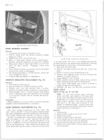
Fig. 6— Windshield Glass, Weatherstrip and Sealing - Conv. Cab
6. Check the relationship of glass to opening as follows:
a. Inside edge of glass to body flange.
b. Outer edge of glass to parallel body metal.
7. Mark areas of body metal or flange to be reformed,
remove glass and correct as necessary.
8. Recheck windshield in its opening and if satisfactory
proceed with installation.
Installation
CAUTION:
Always wear gloves when handling glass.
1. Centralize weatherstrip around edge of glass to avoid
cocking of square corners during assembly.
2. Install a cord around periphery of weatherstrip,
leaving a loop at the top and the loose ends at the
bottom as shown in Figure 9.
3. Place protective covering over plenum grille, front
fenders and hood. Apply sealer to weatherstrip in
areas noted in Figure 7.
4. Place windshield and weatherstrip assembly in open
ing. With one technician lightly pushing in on wind
shield, another technician within the cab should pull
on the cord as follows:
a. Pull on loose ends (fig. 10) until each is within
2" of its respective upper corner.
b. Pull on loop until cord is within 2" of the upper
corners.
c. Finish seating corners by simultaneously pull
ing on both ends of the cord at each corner.
This will insure proper positioning of the critical
upper corners.
d. Apply sealer to upper corners as shown in Figure 6.
OUTSIDE REAR VIEW MIRROR
Rear view mirror installations are shown in Figure 11.
Occasional tightening of mounting and assembly bolts and
screws will sharply decrease occurrence of failure due to
door slamming or road shock.
INSTRUMENT PANEL COMPARTMENT A N D LOCK
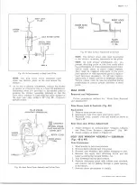
Replacement (Fig. 12)
Removal of the entire assembly including door may be
accomplished by removing ten screws just inside box
and compartment lamp wire (if so equipped). The door
may be removed, leaving the compartment intact, by
removal of four screws and bumper shown in Figure 12.
Access to the door stop bumper is gained by reaching
up beneath instrument panel.
Also shown in Figure 12 is the Lock. Engagement of lock
in striker may be adjusted by loosening striker retaining
screws and moving the striker to desired position.
INSTRUMENT PANEL COVER ASSEMBLY
The instrument panel cover (fig. 13) is secured to the
instrument panel by studs, nuts and screws. The studs
are an integral part of the cover assembly.
Removal and Installation
1. Loosen or remove any necessary instrument panel
items, glove box, etc.
10-30 CHEVROLET TRUCK SERVICE MANUAL
Summary of Contents for 10 1971 Series
Page 1: ......
Page 96: ......
Page 100: ...10 30 CHEVROLET TRUCK SERVICE MANUAL Fig 4 10 30 Series Truck Frame FRAME 2 4 ...
Page 120: ......
Page 203: ...ENGINE 6 25 Fig 22L Engine Mounts 10 30 CHEVROLET TRUCK SERVICE MANUAL ...
Page 215: ...ENGINE 6 37 REAR M O U NT Fig 21V Engine Mounts 10 30 CHEVROLET TRUCK SERVICE MANUAL ...
Page 218: ......
Page 249: ......
Page 324: ......
Page 340: ......
Page 365: ...10 30 CHEVROLET TRUCK SERVICE MANUAL Fig 43 Power Steering Pump M ounting STEERING 9 25 ...
Page 368: ......
Page 386: ......
Page 390: ...ELECTRICAL BODY AND CHASSIS 12 4 10 30 CHEVROLET TRUCK SERVICE MANUAL ...
Page 391: ......
Page 428: ......
Page 432: ......
Page 449: ...SPECIFICATIONS 9 10 30 CHEVROLET TRUCK SERVICE MANUAL ...
Page 463: ......
Page 464: ......
Page 465: ......
Page 466: ......


