T R A N SM ISSIO N A N D CLUTCH 7-31
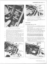
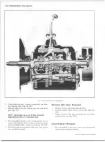
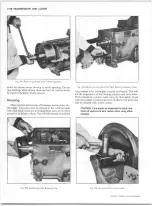
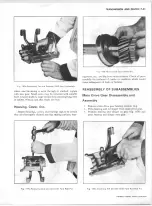
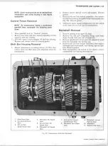
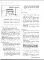
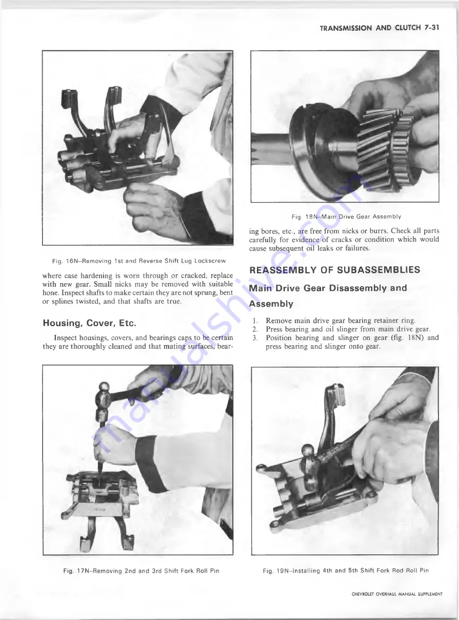
Fig. 16N--Removing 1st and Reverse S h ift Lug Lockscrew
where case hardening is worn through or cracked, replace
with new gear. Small nicks may be removed with suitable
hone. Inspect shafts to make certain they are not sprung, bent
or splines twisted, and that shafts are true.
Housing, Cover, Etc.
Inspect housings, covers, and bearings caps to be certain
they are thoroughly cleaned and that mating surfaces, bear-
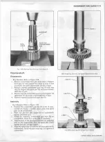
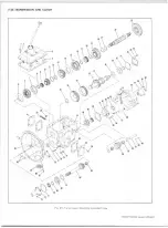
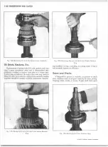
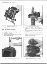
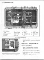
Fig. 18N~M ain Drive Gear A ssem bly
ing bores, etc., are free from nicks or burrs. Check all parts
carefully for evidence of cracks or condition which would
cause subsequent oil leaks or failures.
R E A S S E M B L Y OF S U B A S S E M B L IE S
Main Drive Gear Disassembly and
Assembly
1. Remove main drive gear bearing retainer ring.
2.
Press bearing and oil slinger from main drive gear.
3.
Position bearing and slinger on gear (fig. 18N) and
press bearing and slinger onto gear.
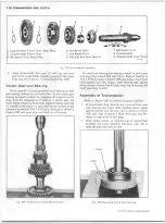
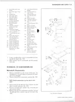
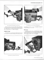
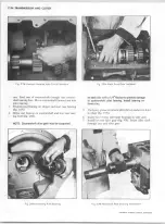
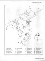
Fig. 17N--Removing 2nd and 3rd S h ift Fork Roll Pin
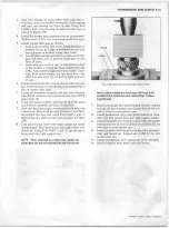
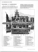
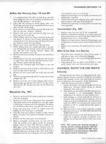
Fig. 19 N— I nsta 11 i ng 4th and 5th S hift Fork Rod Roll Pin
CHEVROLET OVERHAUL M A N U A L SUPPLEMENT
Summary of Contents for 40 60 Series
Page 1: ...40 60 SERIES TRUCK SUPPLEMENT ST 334 72...
Page 86: ......
Page 96: ...n 47 k u m i i i iin I ll II I...
Page 222: ......

