A U TO M A TIC T R A N SM ISSIO N 7-65
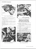
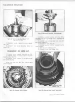
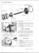
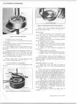
Figure 2 1 — R e m o v in g Front Sea l
Selective washer controlling this end play is
the washer located between pump cover and for
ward clutch housing. If more or le s s washer thick
n ess is required to bring end play within sp ecifica
tions, select proper washer from the following
chart:
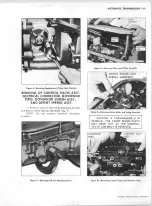
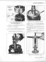
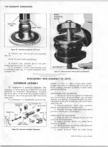
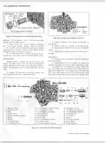
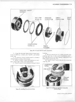
Figure 2 3 — R em o v in g Turbine Shaft a n d F o rw a rd Clutch
NOTE: An oil soaked washer may tend to d is
color, so it w ill be n ecessary to measure washer
for its actual thickness.
R EM O V A L OF OIL PUMP, FORW ARD
CLUTCH, DIRECT CLUTCH, M A N U A L
LINKAGE, A N D GEAR UNIT
1. If n ecessary to replace, pry front seal
from pump (fig.
21
).
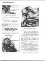
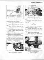
2. Remove pump attaching bolts.
3. Install 3/8"-16 threaded slide hammer
adapters (J-9539) into bolt holes in pump body
with slide hammers (J-6585-2), and remove pump
assem bly from case. (See figure 22 for location of
threaded holes.)
Thickness
Color
.060 - .064
Yellow
.071 - .075
Blue
.082 - .086
Red
.093 - .097
Brown
.104 - .108
Green
.115 - .119
Black
.126 - .130
Purple
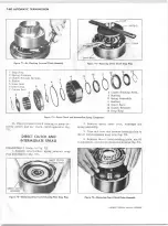
Figure 2 2 — R em o vin g Pum p A ssem bly
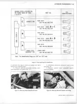
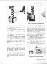
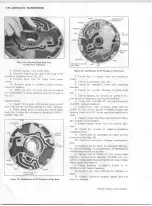
Figure 2 4 — R em o v in g Direct Clutch A sse m b ly
CHEVROLET OVERHAUL M A N U A L SUPPLEMENT
Summary of Contents for 40 60 Series
Page 1: ...40 60 SERIES TRUCK SUPPLEMENT ST 334 72...
Page 86: ......
Page 96: ...n 47 k u m i i i iin I ll II I...
Page 222: ......

