A U TO M A TIC T R A N SM ISSIO N 7-73
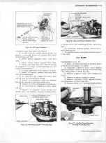
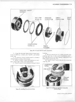
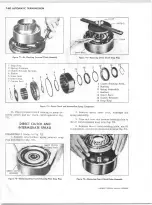
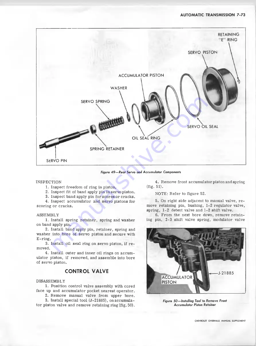
SERVO PIN
ACCUMULATOR PISTON
WASHER
SERVO SPRING
OIL SEAL RING
SPRING RETAINER
SERVO OIL SEAL
Figure 4 9 — R e a r S e rv o a n d A ccu m u la to r Com ponents
INSPECTION
1. Inspect freedom of ring in piston.
2. Inspect fit of band apply pin in servo piston.
3. Inspect band apply pin for scores or cracks.
4. Inspect accumulator and servo pistons for
scoring or cracks.
ASSEMBLY
1. Install spring retainer, spring and washer
on band apply pin.
2. Install band apply pin, retainer, spring and
washer into bore of servo piston and secure with
E -ring.
3. Install oil seal ring on servo piston, if r e
moved.
4. Install outer and inner oil rings on accum
ulator piston, if removed, and assem ble into bore
of servo piston.
CONTROL VALVE
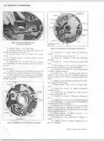
4. Remove front accumulator piston and spring
(fig- 51).
NOTE: Refer to figure 52.
5. On right side adjacent to manual valve, r e
move retaining pin, bushing,
1-2
regulator valve,
spring,
1-2
detent valve and
1-2
shift valve.
6
. From the next bore down, remove retain
ing pin, 2-3 shift valve spring, modulator valve
DISASSEMBLY
1. Position control valve assem bly with cored
face up and accumulator pocket nearest operator.
2. Remove manual valve from upper bore.
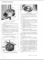
3. Install special tool (J-21885), onaccum ula-
Figure 5 0 — Installing Tool to R e m o v e Front
tor piston valve and remove retaining ring (fig. 50).
A ccu m u la to r Piston Retainer
J-21885
ACCUMULATOR
PISTON
CHEVROLET OVERHAUL M A N U A L SUPPLEMENT
Summary of Contents for 40 60 Series
Page 1: ...40 60 SERIES TRUCK SUPPLEMENT ST 334 72...
Page 86: ......
Page 96: ...n 47 k u m i i i iin I ll II I...
Page 222: ......

