7-78 AU TO M A TIC T R A N SM ISSIO N
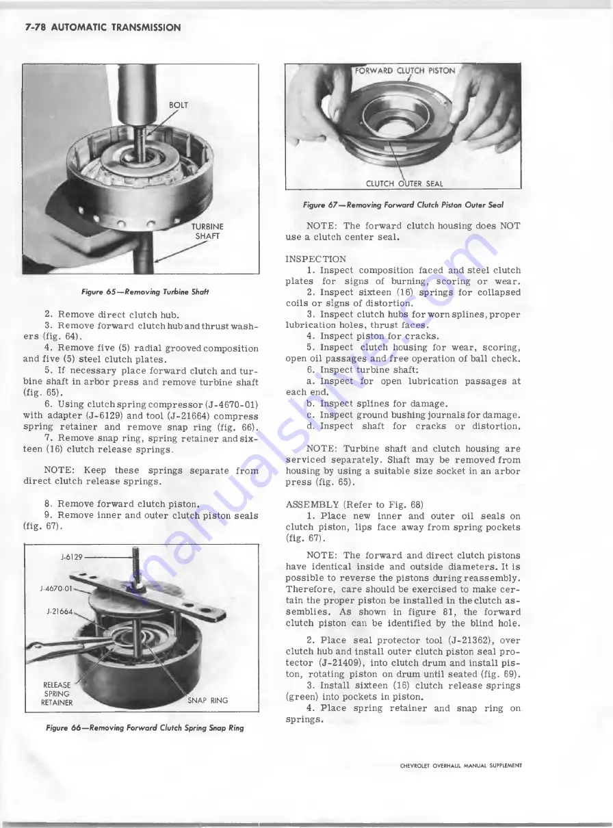
B O L T
T U R B IN E
S H A F T
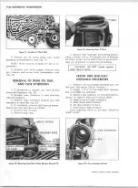
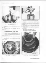
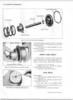
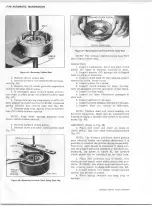
Figure 6 5 — R e m o v in g Turbine Shaft
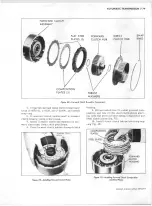
2. Remove direct clutch hub.
3. Remove forward clutch hub and thrust wash
ers (fig. 64).
4. Remove five (5) radial grooved composition
and five (5) steel clutch plates.
5. If necessary place forward clutch and tur
bine shaft in arbor p ress and remove turbine shaft
(fig. 65).
6
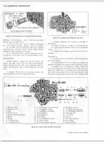
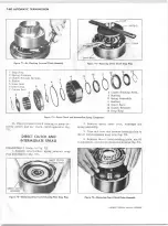
. Using clutch spring com pressor (J-4670-01)
with adapter (J-6129) and tool (J-21664) com press
spring retainer and remove snap ring (fig.
66
).
7. Remove snap ring, spring retainer and s ix
teen (16) clutch release springs.
NOTE: Keep these springs separate from
direct clutch release springs.
8
. Remove forward clutch piston.
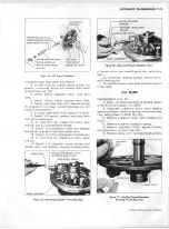
9. Remove inner and outer clutch piston sea ls
(fig. 67).
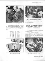
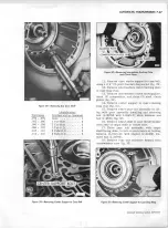
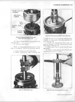
Figure 6 6 — Rem oving F o rw a rd Clutch Spring Snap Ring
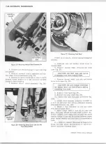
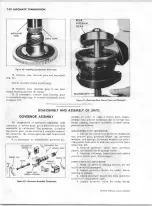
Figure 6 7 — R em o vin g F o rw a rd Clutch Piston O u ter S e a l
NOTE: The forward clutch housing does NOT
use a clutch center seal.
INSPECTION
1. Inspect composition faced and steel clutch
plates for signs of burning, scoring or wear.
2. Inspect sixteen (16) springs for collapsed
co ils or signs of distortion.
3. Inspect clutch hubs for worn splines, proper
lubrication holes, thrust faces.
4. Inspect piston for cracks.
5. Inspect clutch housing for wear, scoring,
open oil passages and free operation of ball check.
6
. Inspect turbine shaft:
a. Inspect for open lubrication p assages at
each end.
b. Inspect splines for damage.
c. Inspect ground bushing journals for damage.
d. Inspect shaft for cracks or distortion.
NOTE: Turbine shaft and clutch housing are
serviced separately. Shaft may be removed from
housing by using a suitable siz e socket in an arbor
p ress (fig. 65).
ASSEMBLY (Refer to Fig.
68
)
1. Place new inner and outer oil se a ls on
clutch piston, lips face away from spring pockets
(fig. 67).
NOTE: The forward and direct clutch pistons
have identical inside and outside diam eters. It is
p ossib le to reverse the pistons during reassem bly.
Therefore, care should be exercised to make c e r
tain the proper piston be installed in the clutch a s
sem b lies. As shown in figure 81, the forward
clutch piston can be identified by the blind hole.
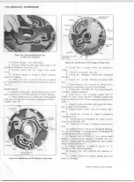
2. Place sea l protector tool (J-21362), over
clutch hub and install outer clutch piston seal pro
tector (J-21409), into clutch drum and install p is
ton, rotating piston on drum until seated (fig. 69).
3. Install sixteen (16) clutch relea se springs
(green) into pockets in piston.
4. Place spring retainer and snap ring on
springs.
CLUTCH OUTER SEAL
J-6129
J-4670-01
J-21664
RELEASE
SPRING
RETAINER
SNAP RING
CHEVROLET O VERHAUL M A N U A L SUPPLEMENT
Summary of Contents for 40 60 Series
Page 1: ...40 60 SERIES TRUCK SUPPLEMENT ST 334 72...
Page 86: ......
Page 96: ...n 47 k u m i i i iin I ll II I...
Page 222: ......

