A UTO M ATIC T R A N SM ISSIO N 7-83
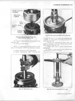
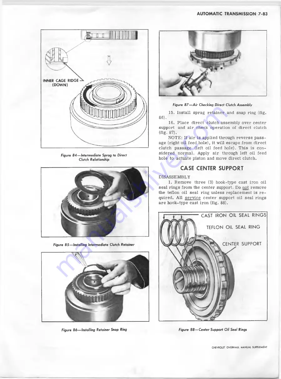
Figure 8 4 — Intermediate S p r a g to Direct
Clutch Relationship
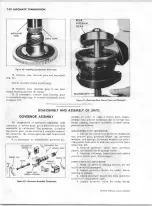
Figure 8 7 — A ir C hecking Direct Clutch A ssem b ly
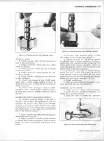
15. Install sprag retainer and snap ring (fig.
86).
16. Place direct clutch assem bly over center
support and air check operation of direct clutch
(fig. 87).
NOTE: If air is applied through reverse p a s s
age (right oil feed hole), it will escape from direct
clutch passage (left oil feed hole). This is con
sidered normal. Apply air through left oil feed
hole to actuate piston and move direct clutch.
CASE CENTER SUPPORT
DISASSEMBLY
1. Remove three (3) hook-type cast iron oil
sea l rings from the center support. Do not remove
the teflon oil seal ring unless replacement is r e
quired. All service center support oil sea l rings
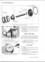
are hook-type cast iron (fig.
88
).
Figure 8 5 — Installing Intermediate Clutch Retainer
CAST IRON OIL SEAL RINGS
TEFLON OIL SEAL RING
CENTER SUPPORT
Figure 8 6 — Installing R etainer Snap Ring
Figure 8 8 — Center S upp ort O il S e a l Rings
CHEVROLET O VERHAUL M A N U A L SUPPLEMENT
Summary of Contents for 40 60 Series
Page 1: ...40 60 SERIES TRUCK SUPPLEMENT ST 334 72...
Page 86: ......
Page 96: ...n 47 k u m i i i iin I ll II I...
Page 222: ......

