7-88 A U TO M A TIC T R A N SM ISSIO N
Figure 101— M o d u lato r A sse m b ly and V a lv e
2.
Inspect O-ring sea l seat for damage.
3. Apply suction to vacuum tube and check for
diaphragm leaks.
4. Check modulator bellows (modulatorplung
er is under pressure - 16 lbs.). If bellows is dam
aged, plunger w ill have very little p ressu re.
5. Inspect modulator valve for nicks or damage.
6
. Check freen ess of valve operation in case
bore.
Manual Shaft Components (Fig. 102)
1. Inspect manual shaft for damaged threads,
rough oil seal surface or loose lever.
2. Inspect inside detent lever for cracks or a
loose pin.
3. Inspect detent roller and spring assem bly.
Case Assembly Inspection (Figs. 103 and 104)
CAUTION: If the case assem bly re
q u ire s replacem ent, m ake sure the ce n te r
s u p p o rt-to -c a s e sp ace r is rem oved fro m
the old case and re in s ta lle d in the new
case.
Figure 102— M a n u a l Shaft Components
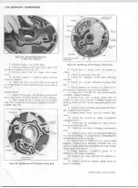
Figure 1 0 3 — C ase P a ssa g e Identification— Front V ie w
1. Inspect case for cracks or broken lugs.
Replace case if cracked or broken.
2. Inspect for internal porosity or cro ss chan
nel leaks in valve body face p assages. Inspect for
porosity or defects in modulator valve bore, case
intake bore, pump case face, etc. Replace case if
internal porosity or damage is found.
3. Inspect for m issing or loose intermediate
clutch cup plug (fig. 103). If loose or m issing, re
place as directed later under "Case Assem bly
Repairs."
4. Inspect for damaged snap ring grooves;
replace case if damaged.
5. Inspect case bushing for presence of oil
lubrication grooves, severe scoring, or wear. If
n ecessary, replace bushing as directed later under
"Case Assem bly Repairs."
6
. Inspect all bolt holes for stripped threads.
Damaged threads can be repaired, u sin gH eli-co ils,
as directed later under "Case Assem bly Repairs."
7. Inspect studs for thread damage, and make
sure they are tight.
NOTE: The two (2) studs at 9 o'clock and 11
o’clock (when viewed from the rear of case and
transm ission in vehicle) are approximately
long
er than the other four (4) studs. These two longer
studs are required to accommodate the parking
brake actuating cable bracket.
Case Assem bly Repairs
Intermediate Clutch Cup Plug Installation
1. With transm ission case in holding fixture,
position with front end facing up.
2. Make sure intermediate clutch cup plug
hole (fig. 103) is free of foreign material such as
dirt, chips, etc.
LINEv DRIVE
MODULATOR
r e v e r s e
X
A
^
o r
' N T ^ A D ' A T E
TO COOLER
PUMP
INTAKE
INTERMEDIATE CLUTCH
CUP PLUG
CHEVROLET OVERHAUL M A N U A L SUPPLEMENT
Summary of Contents for 40 60 Series
Page 1: ...40 60 SERIES TRUCK SUPPLEMENT ST 334 72...
Page 86: ......
Page 96: ...n 47 k u m i i i iin I ll II I...
Page 222: ......

