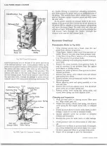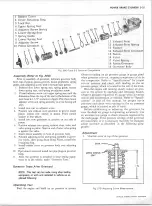
5-14 POW ER BRAKE CYLINDER
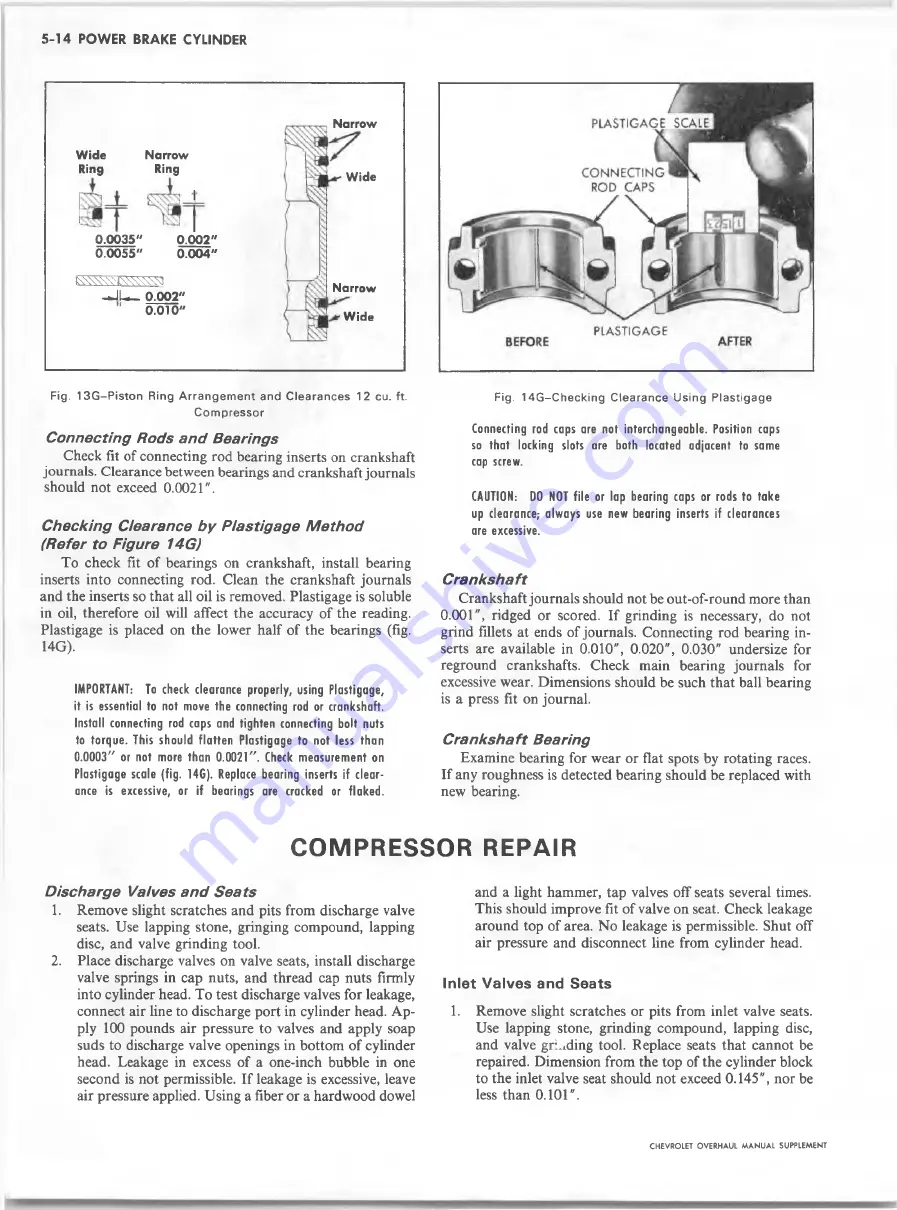
Wide
Narrow
Ring
Ring
0.0035"
0.0 0 2 "
0.0055"
0.004"
iW W W '-'f^W W S
-J L _ 0.002"
0
.
010
"
Narrow
Wide
Narrow
Wide
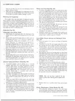
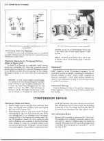
Fig. 13G~Piston Ring A rran ge m ent and Clearances 12 cu. ft.
Com pressor
Connecting R ods a nd Bearings
Check fit of connecting rod bearing inserts on crankshaft
journals. Clearance between bearings and crankshaft journals
should not exceed
0
.
0 0 2 1
".
C h e ckin g Clearance b y P/astigage M e th od
(Refer to Figure 14G)
To check fit of bearings on crankshaft, install bearing
inserts into connecting rod. Clean the crankshaft journals
and the inserts so that all oil is removed. Plastigage is soluble
in oil, therefore oil will affect the accuracy of the reading.
Plastigage is placed on the lower half of the bearings (fig.
14G).
IMPORTANT: To check clearance properly, using Plastigage,
it is essential to not move the connecting rod or crankshaft.
Install connecting rod caps and tighten connecting bolt nuts
to torque. This should flatten Plastigage to not less than
0.0003" or not more than 0.0021". Check measurement on
Plastigage scale (fig. 14G). Replace bearing inserts if clear
ance is excessive, or if bearings are cracked or flaked.
Fig. 14G -C hecking Clearance Using Plastigage
Connecting rod caps are not interchangeable. Position caps
so that locking slots are both located adjacent to same
cap screw.
CAUTION: DO NOT file or lap bearing caps or rods to take
up clearance; always use new bearing inserts if clearances
are excessive.
Crankshaft
Crankshaft journals should not be out-of-round more than
0.001", ridged or scored. If grinding is necessary, do not
grind fillets at ends of journals. Connecting rod bearing in
serts are available in 0.010", 0.020", 0.030" undersize for
reground crankshafts. Check main bearing journals for
excessive wear. Dimensions should be such that ball bearing
is a press fit on journal.
Crankshaft Bearing
Examine bearing for wear or flat spots by rotating races.
If any roughness is detected bearing should be replaced with
new bearing.
C O M P R E S S O R R E P A IR
Discharge Valves a nd Sea ts
1. Remove slight scratches and pits from discharge valve
seats. Use lapping stone, gringing compound, lapping
disc, and valve grinding tool.
2. Place discharge valves on valve seats, install discharge
valve springs in cap nuts, and thread cap nuts firmly
into cylinder head. To test discharge valves for leakage,
connect air line to discharge port in cylinder head. Ap
ply
1 0 0
pounds air pressure to valves and apply soap
suds to discharge valve openings in bottom of cylinder
head. Leakage in excess of a one-inch bubble in one
second is not permissible. If leakage is excessive, leave
air pressure applied. Using a fiber or a hardwood dowel
and a light hammer, tap valves off seats several times.
This should improve fit of valve on seat. Check leakage
around top of area. No leakage is permissible. Shut off
air pressure and disconnect line from cylinder head.
Inlet V a lv e s and S e a t s
1. Remove slight scratches or pits from inlet valve seats.
Use lapping stone, grinding compound, lapping disc,
and valve grinding tool. Replace seats that cannot be
repaired. Dimension from the top of the cylinder block
to the inlet valve seat should not exceed 0.145", nor be
less than
0
.
1 0 1
".
CHEVROLET OVERHAUL M A N U A L SUPPLEMENT
Summary of Contents for 40 60 Series
Page 1: ...40 60 SERIES TRUCK SUPPLEMENT ST 334 72...
Page 86: ......
Page 96: ...n 47 k u m i i i iin I ll II I...
Page 222: ......


