CARBURETORS 6M-1
Section
6 M
CARBURETOR
H O L L E Y 4 1 5 0 G
INDEX
General Description ..................................................... ....6M-1
Repair Procedures..............................................................6M-2
Disassem bly................................................................ ....6M-2
Disassemble into Subassemblies......................... ....6M-2
Disassemble Fuel B o w ls...................................... ....6M-2
Disassemble Metering B odies............................. ....6M-2
Disassemble Secondary Throttle
Operating Assembly ........................................ ....6M-2
Disassemble Main B o d y ...................................... ....6M-2
Disassemble Throttle Body......................................6M-3
Cleaning and Inspection.......................................... ....6M-3
Assembly and Adjustments ........................................
Assemble Throttle B ody...................................... ...
Assemble Main Body .............................................
Assemble Secondary Throttle
Operating Assembly ........................................ ...
Assemble Metering B od ies.....................................
Assemble Fuel Bowls .......................................... ..
Adjust Floats (Preliminary) ............................... ..
Assemble Subassemblies........................................ 6M-9
Adjust Secondary Throttle Valve
Stop Screw ............................................................ 6M-10
G E N E R A L D E S C R I P T I O N
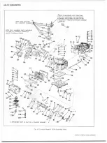
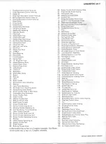
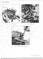
The Holley four-barrel carburetor model 4150G, (fig.
H I) is used with either the 366 or 427 cu. in. truck engine.
This is a four-barrel two-stage carburetor consisting of
eight sub- assemblies. The sub-assemblies are: the throttle
body, the main body, primary and secondary fuel bowls,
primary and secondary metering bodies, secondary throttle
operating assembly, and the governor assembly. The second
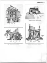
ary throttle operating assembly controls the second stage
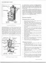
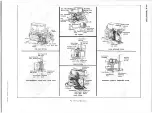
throttle plates (Fig. H2). A vacuum signal to the spring
loaded vacuum diaphragm assembly determines the position
of the throttle plates.
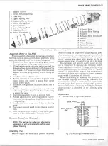
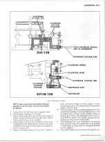
The governor incorporated on this carburetor (fig. H3)
provides a positive means of controlling engine speed. The
throttle lever controls the engine until the governing speed is
reached, at this time the governor assembly adjusts the throt
tle plates to maintain this speed under the various loadings.
A clutch arrangement on the throttle body allows the manual
control below governing speeds.
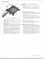
On the Vehicle Governor and Secondary
Diaphragm Control Valve Checks
a. To test governor setting on the service floor, run the
engine up to governor specifications Adjust governor
as necessary.
b.
If there is no governor control, start with step number
1
.
c.
If the engine governs at light load and doesn’t govern
at wide open throttle, the problem is probably in the
dump valve. Go to step number 3.
Step N um ber 1
Disconnect vacuum line at slave unit. Leave dump valve
line attached; speed the engine up to 2200-2400
rpm, wet your finger and place over the vacuum
passage to the distributor. If the engine speed is
reduced to near idle, the problem is in the control
(spinner) valve or the line or fittings to the control
valve.
Ste p N um ber 2
If the job does not return to idle; disconnect the line to
the dump valve and remove the vacuum fitting from
the slave unit. Again speed the engine up to 2200-
2400 rpm and place a wet finger over the vacuum
passage. If the job now returns to near idle, the
problem is in the dump valve line. If it does not
return to idle, the problem is in the slave unit or
vacuum connections or passages behind the slave
unit.
CHEVROLET OVERHAUL M A N U A L SUPPLEMENT
Summary of Contents for 40 60 Series
Page 1: ...40 60 SERIES TRUCK SUPPLEMENT ST 334 72...
Page 86: ......
Page 96: ...n 47 k u m i i i iin I ll II I...
Page 222: ......

